 |
am3zzn00000547
ON-BOARD DIAGNOSTIC SYSTEM TEST MODE [MZ-CD 1.6 (Y6)]
id0102c3100200
|
Diagnostic test mode |
Item |
|---|---|
|
Mode 01
|
Sending diagnostic data (PID data monitor/On-board system readiness test)
|
|
Mode 02
|
Sending freeze frame data
|
|
Mode 03
|
Sending emission-related malfunction code (DTC)
|
|
Mode 04
|
Clearing/resetting emission-related malfunction information
|
|
Mode 06
|
Sending intermittent monitoring system test results (DMTR)
|
|
Mode 07
|
Sending continuous monitoring system test results (pending code)
|
|
Mode 09
|
Request vehicle information
|
Sending Diagnostic Data
PID data monitor
PID/DATA monitor item table
|
Item |
Definition |
Unit/Condition |
|||
|---|---|---|---|---|---|
|
ABS_MSG
|
The CAN communication with the ABS HU/CU
|
Present/
Not Present
|
|||
|
ACCS
|
A/C compressor cycling switch
|
On/Off
|
|||
|
AC_LOWSW
|
A/C compressor cycling switch
|
On/Off
|
|||
|
ALTF
|
Generator field current control duty signal
|
%
|
|||
|
APP
|
APP sensor
|
%
|
|||
|
ARPMDES
|
Target idle speed
|
RPM
|
|||
|
BARO
|
Barometric pressure
|
Pa
|
Bar
|
psi
|
|
|
BOO
|
Brake switch
|
On/Off
|
|||
|
COLP
|
Refrigerant pressure switch (medium pressure switch)
|
On/Off
|
|||
|
DTCCNT
|
DTC count
|
No unit
|
|||
|
ECT
|
ECT sensor
|
°C
|
°F
|
||
|
EGRDC
|
EGR valve
|
%
|
|||
|
EGRVP
|
EGR valve position sensor
|
%
|
|||
|
EOT
|
Engine oil temperature sensor
|
°C
|
°F
|
||
|
FAN_DUTY
|
Fan control duty value
|
%
|
|||
|
FP
|
Fuel pump
|
%
|
|||
|
FRP
|
Fuel pressure sensor
|
Pa
|
Bar
|
psi
|
|
|
FRT
|
Fuel temperature sensor
|
°C
|
°F
|
||
|
GPC
|
Glow plug relay
|
On/Off
|
|||
|
IAT
|
IAT sensor
|
°C
|
°F
|
||
|
IC_MSG
|
The CAN communication with the instrument cluster
|
Present/
Not Present
|
|||
|
MAF
|
MAF sensor
|
g/s
|
|||
|
MAP
|
MAP sensor
|
Pa
|
Bar
|
psi
|
|
|
MIL_DIS
|
Travelled distance since MIL illuminated
|
m
|
mile
|
||
|
OPSW
|
Oil pressure switch
|
On/Off
|
|||
|
RPM
|
Engine speed
|
RPM
|
|||
|
ST_EN_RLY
|
Stater relay
|
Enabled/Disabled
|
|||
|
TIRESIZE
|
Tire revolution per mile
|
rev/mile
|
|||
|
TORQUE
|
Net engine torque
|
Nm
|
|||
|
VBCV
|
VBC solenoid valve
|
%
|
|||
|
VPWR
|
Battery positive voltage
|
V
|
|||
|
VSS
|
Vehicle speed
|
KPH
|
MPH
|
||
Sending Freeze Frame Data
Freeze frame data monitor table
|
Full names |
Unit |
|
|---|---|---|
|
DTC that caused the freeze Frame
|
No unit
|
|
|
Calculated Load Value
|
%
|
|
|
Coolant temperature
|
°C
|
°F
|
|
Intake manifold pressure
|
kPa
|
|
|
Engine speed
|
rpm
|
|
|
Vehicle speed
|
km/h
|
mph
|
|
Intake air temperature
|
°C
|
°F
|
|
Air flow rate
|
g/s
|
|
|
Throttle position sensor*
|
%
|
|
|
Fuel rail pressure
|
kPa
|
|
Sending Emission-related Malfunction Code
DTC table (PCM)
|
DTC No. |
Condition |
|---|---|
|
C1194
|
DSC continuous operation fault
|
|
P0033*1
|
Air bypass valve position sensor open circuit
|
|
P0045
|
Variable boost control (VBC) solenoid valve control circuit open
|
|
P0046
|
Variable boost control (VBC) solenoid valve range/performance problem
|
|
P0047
|
Variable boost control (VBC) solenoid valve control circuit low input
|
|
P0048
|
Variable boost control (VBC) solenoid valve control circuit high input
|
|
P0069
|
MAP sensor and BARO sensor signal correlation error
|
|
P0087
|
Fuel rail pressure - too low
|
|
P0088
|
Fuel rail pressure - too high
|
|
P0089
|
Fuel pressure regulator performance
|
|
P0097*1
|
Intake air temperature (IAT) sensor No.2 circuit low input
|
|
P0098*1
|
Intake air temperature (IAT) sensor No.2 circuit high input
|
|
P0100
|
Mass air flow (MAF) sensor circuit malfunction
|
|
P0101
|
Mass air flow (MAF) sensor range/performance problem
|
|
P0102
|
Mass air flow (MAF) sensor circuit low input
|
|
P0103
|
Mass air flow (MAF) sensor circuit high input
|
|
P0112
|
Intake air temperature (IAT) sensor circuit low input
|
|
P0113
|
Intake air temperature (IAT) sensor circuit high input
|
|
P0116
|
Engine coolant temperature (ECT) sensor range/performance problem
|
|
P0117
|
Engine coolant temperature (ECT) sensor circuit low input
|
|
P0118
|
Engine coolant temperature (ECT) sensor circuit high input
|
|
P0120
|
Accelerator pedal position (APP) sensor circuit malfunction
|
|
P0121
|
|
|
P0122
|
Accelerator pedal position (APP) sensor circuit low input
|
|
P0123
|
Accelerator pedal position (APP) sensor circuit high input
|
|
P0182
|
Fuel temperature sensor circuit low input
|
|
P0183
|
Fuel temperature sensor circuit high input
|
|
P0191
|
Fuel pressure sensor range/performance problem
|
|
P0192
|
Fuel pressure sensor circuit low input
|
|
P0193
|
Fuel pressure sensor circuit high input
|
|
P0201
|
Fuel injector No.1 control circuit open
|
|
P0202
|
Fuel injector No.2 control circuit open
|
|
P0203
|
Fuel injector No.3 control circuit open
|
|
P0204
|
Fuel injector No.4 control circuit open
|
|
P0220
|
Accelerator pedal position (APP) sensor circuit malfunction
|
|
P0221
|
|
|
P0222
|
Throttle pedal position switch B circuit low input
|
|
P0223
|
Throttle pedal position switch B circuit high input
|
|
P022A*1
|
Air bypass valve actuator control circuit open
|
|
P022B*1
|
Air bypass valve position sensor circuit low input
|
|
P022C*1
|
Air bypass valve position sensor circuit high input
|
|
P0234
|
Turbocharger over boost condition
|
|
P0236
|
Manifold absolute pressure (MAP) sensor range/performance problem
|
|
P0237
|
Manifold absolute pressure (MAP) sensor circuit low input
|
|
P0238
|
Manifold absolute pressure (MAP) sensor circuit high input
|
|
P024A*1
|
Persistent air bypass valve governor deviation
|
|
P024B*1
|
Air bypass valve stuck or jammed error
|
|
P024E*1
|
Air bypass valve position sensor circuit low input
|
|
P024F*1
|
Air bypass valve position sensor circuit high input
|
|
P0251
|
The fuel metering valve control circuit open
|
|
P0252
|
The fuel metering valve control range/performance problem
|
|
P0253
|
The fuel metering valve control circuit low input
|
|
P0254
|
The fuel metering valve control circuit high input
|
|
P0299
|
Turbocharger under boost
|
|
P0313
|
Misfire detected with low fuel
|
|
P0335
|
Crankshaft position (CKP) sensor circuit malfunction
|
|
P0336
|
Crankshaft position (CKP) sensor circuit range/performance problem
|
|
P0339
|
Crankshaft position (CKP) sensor circuit intermittent concern
|
|
P0340
|
Camshaft position (CMP) sensor circuit malfunction
|
|
P0341
|
Camshaft position (CMP) sensor circuit range/performance problem
|
|
P0344
|
Camshaft position (CMP) sensor circuit intermittent concern
|
|
P0380
|
Glow plug circuit malfunction
|
|
P0401
|
EGR flow insufficient detected
|
|
P0402
|
EGR flow excessive detected
|
|
P0403
|
EGR valve actuator circuit malfunction
|
|
P0404
|
EGR valve actuator control circuit range/performance problem
|
|
P0405
|
EGR valve position sensor circuit low input
|
|
P0406
|
EGR valve position sensor circuit high input
|
|
P0407*1
|
Intake throttle valve control circuit low input
|
|
P0408*1
|
Intake throttle valve control circuit high input
|
|
P0425*1
|
Catalyst exhaust gas temperature sensor circuit range/performance problem
|
|
P0426*1
|
|
|
P0427*1
|
Catalyst exhaust gas temperature sensor circuit low input
|
|
P0428*1
|
Catalyst exhaust gas temperature sensor circuit high input
|
|
P042E
|
EGR valve stuck open
|
|
P042F
|
EGR valve stuck closed
|
|
P0480
|
Fan control circuit malfunction
|
|
P0483
|
Fan control module range/performance problem
|
|
P0487*1
|
Intake throttle valve control circuit malfunction
|
|
P0488*1
|
Intake throttle valve control range/performance
|
|
P0489
|
EGR control circuit range / performance (swerves to open side)
|
|
P0490
|
EGR control circuit range / performance (swerves to close side)
|
|
P0500
|
Vehicle speed signal problem
|
|
P0504
|
Brake light switch and brake signal correlation
|
|
P0562
|
Battery voltage low input
|
|
P0563
|
Battery voltage high input
|
|
P0606
|
PCM malfunction
|
|
P060B
|
|
|
P061B
|
|
|
P061C
|
|
|
P062B
|
|
|
P062D
|
|
|
P0615
|
Starter relay circuit malfunction
|
|
P0616
|
Starter relay circuit low input
|
|
P0617
|
Starter relay circuit high input
|
|
P0620
|
Generator control circuit malfunction
|
|
P0A3B
|
Generator over temperature
|
|
P0642
|
Diesel particulate filter differential pressure sensor circuit or MAP sensor circuit low input
|
|
P0643
|
Diesel particulate filter differential pressure sensor circuit or MAP sensor circuit high input
|
|
P0645
|
A/C clutch relay circuit malfunction
|
|
P0646
|
A/C clutch relay circuit low input
|
|
P0647
|
A/C clutch relay circuit high input
|
|
P0652
|
EGR throttle valve position sensor circuit or air bypass valve position sensor circuit or CMP sensor circuit or CKP sensor circuit low input
|
|
P0653
|
EGR throttle valve position sensor circuit or air bypass valve position sensor circuit or CMP sensor circuit or CKP sensor circuit high input
|
|
P0691
|
Fan control module circuit low input
|
|
P0692
|
Fan control module circuit high input
|
|
P0698
|
EGR valve position sensor circuit or fuel pressure sensor circuit low input
|
|
P0699
|
EGR valve position sensor circuit or fuel pressure sensor circuit high input
|
|
P0704
|
Clutch pedal position (CPP) switch input circuit malfunction
|
|
P1000
|
OBD system readiness test not complete
|
|
P1101
|
Mass air flow (MAF) sensor out of self test range
|
|
P1102
|
Mass air flow (MAF) sensor in range but lower than expected
|
|
P1103
|
Mass air flow (MAF) sensor in range but higher than expected
|
|
P1145
|
Calculated torque error
|
|
P115A
|
Low fuel level - forced limited power
|
|
P115B
|
Low fuel level - forced engine shutdown
|
|
P115D
|
Mass air flow (MAF) sensor signal offset
|
|
P1180
|
Fuel delivery system-low
|
|
P1181
|
Fuel delivery system-high
|
|
P1187*1
|
Variant selection
|
|
P1201
|
Fuel injector No.1 circuit malfunction
|
|
P1202
|
Fuel injector No.2 circuit malfunction
|
|
P1203
|
Fuel injector No.3 circuit malfunction
|
|
P1204
|
Fuel injector No.4 circuit malfunction
|
|
P1209
|
Fuel pressure peak delta test error
|
|
P1210
|
Fuel pressure higher than desired when engine off
|
|
P1211
|
Fuel pressure higher or lower than desired
|
|
P1212
|
Fuel pressure lower than desired
|
|
P1244
|
Generator load high input
|
|
P1245
|
Generator load low input
|
|
P1259*1
|
Instrument cluster to PCM signal error
|
|
P1260
|
Immobilizer system problem
|
|
P1295
|
Injector multiple faults
|
|
P138A
|
Glow plug relay system voltage
|
|
P138B
|
Glow plug relay system voltage
|
|
P138C*1
|
Air bypass valve position sensor minimum/maximum stop
|
|
P1391
|
Glow plug circuit low input
|
|
P1392
|
Glow plug circuit high input
|
|
P1395
|
Glow plug monitor error
|
|
P1402
|
EGR metering orifice restricted
|
|
P1412
|
EGR valve frozen
|
|
P1551
|
Fuel injector No.1 range/performance malfunction
|
|
P1552
|
Fuel injector No.2 range/performance malfunction
|
|
P1553
|
Fuel injector No.3 range/performance malfunction
|
|
P1554
|
Fuel injector No.4 range/performance malfunction
|
|
P1574
|
Accelerator pedal position (APP) sensor output disagree
|
|
P1577
|
|
|
P1602
|
Immobilizer/PCM communication error
|
|
P1603
|
EEPROM malfunction
|
|
P1608
|
PCM processor
|
|
P1609
|
|
|
P1621*1
|
Immobilizer system code word does not match
|
|
P1622*1
|
Key ID number does not match
|
|
P1630
|
Internal Vref
|
|
P1631
|
PCM control relay (power hold)
|
|
P1632
|
Smart generator malfunctions sensor/circuit
|
|
P1635
|
Tire/axle out of acceptable range
|
|
P1639
|
Vehicle identification block corrupted or not programmed
|
|
P1675
|
Injector correction data not programmed
|
|
P1676
|
Injector correction data incorrect
|
|
P1719
|
Engine torque signal
|
|
P1934
|
Vehicle speed signal problem
|
|
P1935
|
BOO switch input circuit malfunction
|
|
P1936
|
Clutch pedal position (CPP) switch input circuit malfunction
|
|
P193B
|
Accelerator pedal position (APP) sensor circuit malfunction
|
|
P2002*1
|
Diesel particulate trap efficiency below threshold
|
|
P2141*1
|
Intake throttle valve actuator circuit low
|
|
P2142*1
|
Intake throttle valve actuator circuit high
|
|
P2227
|
BARO sensor range/performance problem
|
|
P2228
|
BARO sensor circuit low input
|
|
P2229
|
BARO sensor circuit high input
|
|
P2279
|
Intake-air system leak
|
|
P242F
|
Diesel particulate filter restriction - ash accumulation
|
|
P2453*1
|
Diesel particulate filter differential pressure sensor range/performance problem
|
|
P2454*1
|
Diesel particulate filter differential pressure sensor circuit low input
|
|
P2455*1
|
Diesel particulate filter differential pressure sensor circuit high input
|
|
P2458
|
Diesel particulate filter regeneration duration
|
|
P2459
|
Diesel particulate filter regeneration frequency
|
|
P2530
|
Engine switch run position circuit malfunction
|
|
P2552
|
Throttle/fuel inhibit circuit / open circuit
|
|
P2554
|
Throttle/fuel inhibit circuit low
|
|
P2555
|
Throttle/fuel inhibit circuit high
|
|
P2584*1
|
Fuel additive control module MIL request
|
|
P2585*1
|
Fuel additive control module warning lamp request
|
|
U0416
|
Invalid data received from DSC CM
|
DTC table (fuel additive control module)
|
DTC No. |
Condition |
|---|---|
|
B1317
|
Fuel additive control module B+ voltage high
|
|
B1318
|
Fuel additive control module B+ voltage low
|
|
B1342
|
Fuel additive control module malfunction
|
|
B2477
|
Fuel additive control module programming error
|
|
P1922
|
Fuel Additive Level Circuit
|
|
P1923
|
Fuel Additive Level Circuit Range/Performance
|
|
P1927
|
Fuel additive level too low/empty
|
|
P1928
|
Fuel additive pump control circuit open
|
|
P1930
|
Fuel additive pump control circuit low
|
|
P1931
|
Fuel additive pump control circuit high
|
|
P1932
|
Fuel additive minimum level
|
|
P2409
|
Fuel-filler switch circuit range/performance
|
|
P2410
|
Fuel-filler switch circuit low
|
|
P2411
|
Fuel-filler switch circuit high
|
Sending Continuous Monitoring System Test Results
1-drive cycle type
2-drive cycle type
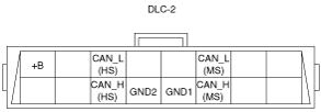
DLC-2 Outline
am3zzn00000547
|
|
Terminal name |
Function |
|---|---|
|
B+
|
Battery positive voltage
|
|
CAN_H (HS)
|
CAN communication line (HS)
|
|
CAN_L (HS)
|
CAN communication line (HS)
|
|
GND1
|
Ground (chassis)
|
|
GND2
|
Ground (signal)
|
|
CAN_H (MS)
|
CAN communication line (MS)
|
|
CAN_L (MS)
|
CAN communication line (MS)
|