CRANKSHAFT, MAIN BEARING CONSTRUCTION[LF, L3]
id0110a0100800
• A five axle-hole, four counter weight cast iron crankshafts have been adopted.
• There is no positioning key where the crankshaft sprocket and crankshaft pully are installed. The crankshaft sprocket must be installed using the SST with the No.1 cylinder aligned with TDC position. Tightening pressure on the tightening bolt is used to secure the crankshaft sprocket and crankshaft pulley.
• An oil line for supplying oil to each journal is provided in the crankshaft. Crank pins and fillets on both sides of the journal are rolled to bear heavy loads.
|
1
|
Oil passage
|
|
2
|
Fillet roll area
|
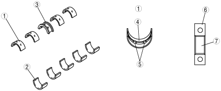
• Upper and lower main bearings are made of aluminum alloy and the upper side No.3 journal bearing is integrated with the thrust bearing. The upper main bearing has oil grooves and oil holes.
• There is no upper and lower bearings positioning tab for installing the main journal.
• Measure and attach the main bearings (upper and lower) so that they are positioned at the center of the main bearing cap.
|
1
|
Upper main bearing
|
|
2
|
Lower main bearing
|
|
3
|
Thrust bearing
|
|
4
|
Upper main bearing oil groove
|
|
5
|
Oil hole
|
|
6
|
Main bearing cap
|
|
7
|
Main bearing
|
• The main bearing can be selected from three types including the standard, 0.25 mm {0.01 in} over size and 0.50 mm {0.02 in} over size.