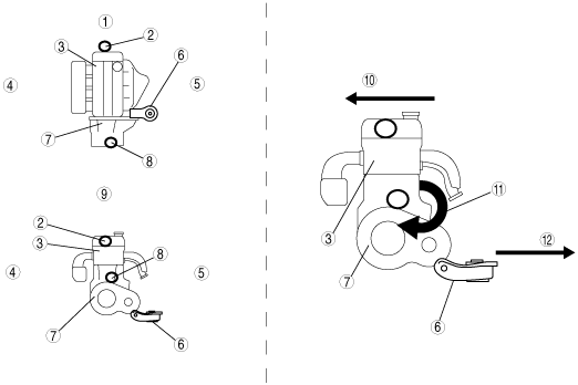
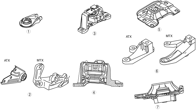
ENGINE MOUNT CONSTRUCTION[LF, L3]


id0110a0102600

•  The No.1 engine mounting rubber regulates backlash from the powertrain.
•  The No.3 engine mounting rubber is oil-filled for noise reduction and vibration isolation.
•  The installation structure of the No.4 engine mount has been simplified for serviceability improvement.
am3zzn00001471

1
No.1 engine mount rubber
2
No.1 engine mount bracket
3
No.3 engine mount rubber
4
No.3 engine mount rubber sectional view
5
No.4 engine mount rubber
6
No.4 engine mount bracket
7
No.4 engine mount rubber sectional view

•  The engine is supported at the following three points: front part of the engine (No.3 engine mounting), one side of the transaxle (No.1 engine mounting), and rear upper part of the transaxle (No.4 engine mounting). The supporting point at the side of the transaxle (No.1 engine mounting) has been set at the lowest edge of the transaxle. With this layout, No.1 engine mounting absorbs the rotation force, generated under the engine torque fluctuation and transmitted to the powertrain, and distributes the rotation force to the front and rear part of the engine (pendulum).
am3zzn00001472

1
Powertrain system upper surface
2
No.3 engine mount
3
Engine
4
Vehicle front
5
Vehicle rear
6
No.1 engine mount
7
Transaxle
8
No.4 engine mount
9
Powertrain system back
10
Engine front
11
Torque
12
Engine back