 |
b3e0110t025
VARIABLE VALVE TIMING MECHANISM CONSTRUCTION[ZJ, ZY, Z6]
id0110b1120700
b3e0110t025
|
|
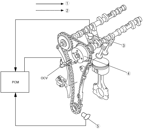
1
|
Electric signal
|
|
2
|
Hydraulic pressure
|
|
3
|
CMP sensor
|
|
4
|
Variable valve timing actuator
|
|
5
|
CKP sensor
|
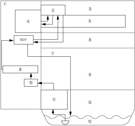
Hydraulic Pressure Flow Diagram
b3e0110t026
|
|
1
|
Engine front cover
|
|
2
|
Camshaft cap
|
|
3
|
Cylinder head cover
|
|
4
|
Variable valve timing actuator
|
|
5
|
Intake camshaft
|
|
6
|
Cylinder head
|
|
7
|
Drain
|
|
8
|
Oil passage in engine front cover
|
|
9
|
Cylinder block
|
|
10
|
Oil filter
|
|
11
|
Oil pump
|
|
12
|
Oil pan
|
|
13
|
Oil
|
|
Variable valve timing actuator
|
• Continuously modifies the phases of the intake camshaft and crankshaft at the forward end of the intake camshaft using hydraulic pressure from the OCV.
|
|
OCV
|
• Operated by current (duty signal) from the PCM. Controls the hydraulic oil passages to the variable valve timing actuator.
|
|
CKP sensor
|
• Inputs engine revolution signal to the PCM.
|
|
CMP sensor
|
• Inputs cylinder identification signal to the PCM.
|
|
PCM
|
• Controls the OCV so that optimum valve timing is obtained according to engine operation conditions.
|