ENGINE TUNE-UP[ZJ, ZY, Z6]
id0110b1800600
Engine Tune-up Preparation
Without throttle valve actuator
1. Warm up the engine to normal operating temperature.
- (1) Increase the engine speed to 2,500—3,000 rpm until the cooling fan starts running.
-
- (2) When the cooling fan starts running, release the accelerator pedal and wait until the cooling fan stops running.
-
2. Verify the following:
-
• ATX: Selector lever is in P or N position.
• MTX: Shift lever is in neutral position.
3. Turn off all electrical loads.
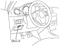
4. Connect the M-MDS to the DLC-2.
5. Turn the test mode on using a simulation function.
6. Verify that the idle speed is within the specification using the RPM DATA MONITOR function.
-
• If not within the specification, adjust the idle speed.
-
Idle speed (ATX)
-
Z6: 700—800 rpm
-
Idle speed (MTX)
-
ZJ: 690—790 rpm
Z6: 640—740 rpm
With throttle valve actuator
1. Warm up the engine to normal operating temperature.
- (1) Increase the engine speed to 2,500—3,000 rpm until the cooling fan starts running.
-
- (2) When the cooling fan starts running, release the accelerator pedal and wait until the cooling fan stops running.
-
2. Verify that no DTCs are available.
3. Turn off all electrical loads.
4. Connect the M-MDS to the DLC-2.
5. Turn the test mode on using a simulation function.
Ignition Timing Inspection
-
Note
-
• The ignition timing cannot be adjusted.
• The M-MDS is required to verify the ignition timing.
• Use a timing light that can detect the primary ignition signal.
Except U.K. specs.
1. Complete the engine tune-up preparation.
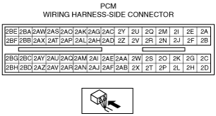
2. Remove the PCM connector cover.
3. By referring to the following procedure, connect the timing light to the PCM terminal 2A (Without throttle valve actuator), 2D (With throttle valve actuator) wire.
-
Caution
-
• To prevent poor contact at the connector terminal, be careful not to pull the wire on the connector side.
-
Note
-
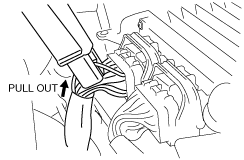
• Pull out the wire 20—30 mm so that the pickup clip of the timing light can be connected. After the ignition timing inspection, bundle the pulled out wire back together with other wires using tape.
- (1) Pull the PCM terminal 2A (Without throttle valve actuator), 2D (With throttle valve actuator) wire out of the bundle (pull the bundled side only, not the connector side).
-
- (2) Connect the pickup clip of the timing light to the PCM terminal 2A (Without throttle valve actuator), 2D (With throttle valve actuator) wire.
-
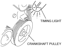
4. Verify that the crankshaft pulley alignment mark (white) is within the specification.
-
Ignition timing (Test mode on)
-
BTDC 9—11 °
5. Turn the test mode off using a simulation test.
6. Using the timing light, verify again that the crankshaft pulley alignment mark (white) is within the specification.
-
• If not within the specification, inspect the following parts:
-
― CMP sensor
― CKP sensor
― TP sensor
― ECT sensor
― TR switch (ATX)
― Neutral/clutch switch (MTX)
-
Ignition timing (Test mode off)
-
BTDC 6—18 °
U.K. specs.
1. Complete the engine tune-up preparation.
2. Connect the pickup clip of the timing light to the ignition coil terminal A wire.
3. Verify that the crankshaft pulley alignment mark (white) is within the specification.
-
Ignition timing (Test mode on)
-
BTDC 9—11 °
4. Turn the test mode off using a simulation test.
5. Using the timing light, verify again that the crankshaft pulley alignment mark (white) is within the specification.
-
• If not within the specification, inspect the following parts:
-
― CMP sensor
― CKP sensor
― TP sensor
― ECT sensor
― TR switch (ATX)
― Neutral/clutch switch (MTX)
-
Ignition timing (Test mode off)
-
BTDC 6—18 °
Idle Speed Inspection
Without throttle valve actuator
-
Caution
-
• Changing the TAS while attempting to adjust the idle speed could cause an engine malfunction. Do not change the TAS adjustment position.
1. Complete the engine tune-up preparation.
2. Verify that the ignition timing is within the specification. (See Ignition Timing Inspection.)
3. Verify that the idle speed is within the specification using the RPM DATA MONITOR function.
-
-
Idle speed (ATX)
-
Z6: 700—800 rpm
-
Idle speed (MTX)
-
ZJ: 690—790 rpm
Z6: 640—740 rpm
4. Verify that the idle speed is within the specification when each load is applied. (The speed decrease just after the load is applied is not considered.)
-
• If not within the specification with any of the specified loads applied, inspect the IAC valve.
• If not within the specification when a specified load is applied, inspect the related input parts, wiring harnesses, and connectors.
-
Idle speed [ZJ MTX (Neutral position)]
-
No load: 690—790 rpm
Electrical loads on*1 (34—42 A): 700—800 rpm
Electrical loads on*1 (more than 42 A): 700—800 rpm
A/C on (Low load*2): 700—800 rpm
A/C on (High load*3): 700—800 rpm
P/S on: 700—800 rpm
-
Idle speed [Z6 ATX (N position)]
-
No load: 700—800 rpm
Electrical loads on*1 (34—42 A): 700—800 rpm
Electrical loads on*1 (more than 42 A): 700—800 rpm
A/C on (Low load*2): 700—800 rpm
A/C on (High load*3): 700—800 rpm
P/S on: 700—800 rpm
-
Idle speed [Z6 ATX (D range)]
-
No load: 650—750 rpm
Electrical loads on*1 (34—42 A): 650—750 rpm
Electrical loads on*1 (more than 42 A): 670—770 rpm
A/C on (Low load*2): 650—750 rpm
A/C on (High load*3): 700—800 rpm
P/S on: 700—800 rpm
-
Idle speed [Z6 MTX (Neutral position)]
-
No load: 640—740 rpm
Electrical loads on*1 (34—42 A): 650—750 rpm
Electrical loads on*1 (more than 42 A): 700—800 rpm
A/C on (Low load*2): 650—750 rpm
A/C on (High load*3): 700—800 rpm
P/S on: 700—800 rpm
*1 :Generator generating current value.
*2 :Refrigerant pressure switch (middle pressure switch) is off.
*3 :Refrigerant pressure switch (middle pressure switch) is on.
With throttle valve actuator
1. Perform the “Engine Tune-up Preparation, With throttle valve actuator”. (See Engine Tune-up Preparation.)
-
Note
-
• Idle speed is not adjustable.
• Idle speed verification requires M-MDS.
2. Verify that the idle speed (M-MDS: RPM PID) is within the specification using M-MDS.
-
-
Idle speed [ZY ATX (N position)]
-
No load: 600—700 rpm
Electrical loads on*1 (34—42 A): 650—750 rpm
Electrical loads on*1 (more than 42 A): 700—800 rpm
A/C on (Low load*2): 650—750 rpm
A/C on (High load*3): 670—770 rpm
-
Idle speed [ZY MTX (Neutral position)]
-
No load: 600—700 rpm
Electrical loads on*1 (34—42 A): 650—750 rpm
Electrical loads on*1 (more than 42 A): 700—800 rpm
A/C on (Low load*2): 650—750 rpm
A/C on (High load*3): 700—800 rpm
*1 :Generator generating current value.
*2 :Refrigerant pressure switch (middle pressure switch) is off.
*3 :Refrigerant pressure switch (middle pressure switch) is on.
Idle Speed Adjustment
Without throttle valve actuator
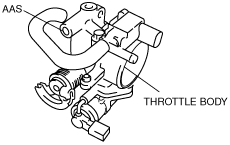
1. Adjust the idle speed to within the specification by turning the AAS after verifying that the ignition timing is within the specification. (See Idle Speed Inspection, Without throttle valve actuator.)
Idle Mixture Inspection
1. Warm up the engine to normal operating temperature.
- (1) Increase the engine speed to 2,500—3,000 rpm until the cooling fan starts running.
-
- (2) When the cooling fan starts running, release the accelerator pedal and wait until the cooling fan stops running.
-
2. Verify that the idle speed and ignition timing are within the specification. (See Ignition Timing Inspection.) (See Idle Speed Inspection.)
3. Insert an exhaust gas analyzer into the tailpipe.
4. Verify that the CO and HC concentrations are within the regulation.
-
Idle Mixture
-
• HC concentration: Within the regulation
• CO concentration: Within the regulation