 |
am3zzn00001293
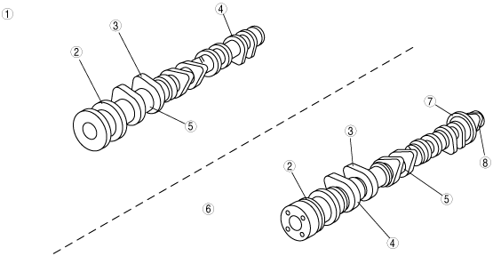
CAMSHAFT CONSTRUCTION[L3 Turbo]
id0110b3101300
Camshaft specification
|
Item |
Specification |
||||
|---|---|---|---|---|---|
|
Intake |
Exhaust |
||||
|
Lift
|
(mm {in})
|
9.1 {0.35}
|
7.8 {0.31}
|
||
|
Overlap
|
(°)
|
5―35
|
|||
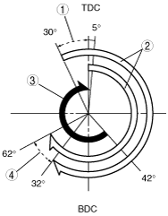
Valve timing
am3zzn00001293
|
|
1
|
Variable domain
|
|
2
|
Intake air
|
|
3
|
Exhaust air
|
|
4
|
Variable domain
|
am3zzn00001294
|
|
1
|
Exhaust camshaft
|
|
2
|
Thrust
|
|
3
|
Cam nose
|
|
4
|
Cam heel
|
|
5
|
Cam journal
|
|
6
|
Intake camshaft
|
|
7
|
CMP sensor detection lobe
|
|
8
|
High pressure fuel pump drive cam
|
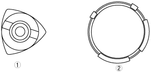
am3zzn00001295
|
|
1
|
High pressure fuel pump drive CAM
|
|
2
|
CMP sensor detection lobes
|
acxuun00000127
|