BALANCER UNIT CONSTRUCTION/OPERATION[L3 Turbo]
id0110b3101700
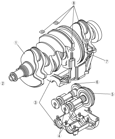
Construction
• The balancer unit consists of two balancer shafts (No.1 and No.2) with weights, the balancer unit case and the adjust shim which adjusts the amount of backlash in the crankshaft.
• The two balancer shafts (No.1 and No.2) are driven by the drive gear which is attached to the crankshaft.
• The balancer unit cannot be disassembled because it is a precision unit.
Operation
• The rotary motion is transmitted from the drive gear, which is between the back of the No.3 cylinder and No.4 main journal, directly to the No.1 balance shaft with driven gear. Then the balance unit transmits the rotation motion to the No.2 balance shaft. The ratio of gears, which are attached to the No.1 and No. 2 balancer shafts, has been set so that the gear rotates at twice the velocity of the crankshaft. The rotation velocity of the balancer shaft counterbalances (generates force in the opposite direction) the rotation inertial force (secondary inertial rotation force) from the crankshaft.
|
1
|
Crankshaft
|
|
2
|
Engine front
|
|
3
|
Balancer unit case
|
|
4
|
Weight
|
|
5
|
No.1 balance shaft with driven gear
|
|
6
|
No.2 balance shaft
|
|
7
|
Drive gear
|
|
8
|
Adjust shim
|
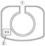
• Replace the adjust shim to adjust backlash. There are 40 kinds of adjuster shim depending on the thickness. The adjuster shim can be determined by checking the engraved identification mark (2 digits) on it.
|
1
|
Adjust shim
|
|
2
|
Engraved identification mark (2 digits)
|