 |
am3zzn00001303
VARIABLE VALVE TIMING MECHANISM CONSTRUCTION/OPERATION[L3 Turbo]
id0110b3102000
Component and Function
|
Variable valve timing actuator
|
• Continuously modifies the phases of the intake camshaft and crankshaft at the forward end of the intake camshaft using hydraulic pressure from the oil control valve (OCV).
|
|
OCV
|
• Operated by current (duty signal) from the PCM. Switches the hydraulic oil passages to the variable valve timing actuator.
|
|
CKP sensor
|
• Input the engine revolution signal to the PCM.
|
|
CMP sensor
|
• Inputs the cylinder identification signal to the PCM.
|
|
PCM
|
• Controls the OCV so that optimum valve timing is obtained according to engine operation conditions.
|
Operation outline
am3zzn00001303
|
|
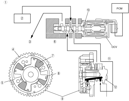
1
|
Hydraulic pressure flow
|
|
2
|
Oil pump
|
|
3
|
Housing
|
|
4
|
Case
|
|
5
|
Oil pan
|
|
6
|
To valve timing advance chamber
|
|
7
|
Rotor
|
|
8
|
Valve timing advance chamber
|
|
9
|
Variable valve timing actuator
|
|
10
|
Spool valve
|
|
11
|
From valve timing retard chamber
|
|
12
|
Camshaft
|
am3zzn00001304
|
|
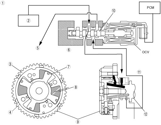
1
|
Hydraulic pressure flow
|
|
2
|
Oil pump
|
|
3
|
Oil pan
|
|
4
|
Housing
|
|
5
|
Case
|
|
6
|
From valve timing advance chamber
|
|
7
|
Valve timing retard chamber
|
|
8
|
Rotor
|
|
9
|
Variable valve timing actuator
|
|
10
|
Spool valve
|
|
11
|
To valve timing retard chamber
|
|
12
|
Camshaft
|
am3zzn00001305
|
|
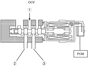
1
|
Oil pump
|
|
2
|
To valve timing advance chamber
|
|
3
|
To valve timing retard chamber
|