 |
am3zzn00000394
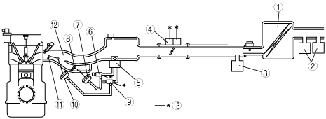
INTAKE-AIR SYSTEM DIAGRAM[LF, L3]
id0113b3102200
am3zzn00000394
|
|
1
|
Air cleaner
|
|
2
|
Resonance chamber (fresh-air duct side)
|
|
3
|
Resonance chamber (air cleaner side)
|
|
4
|
Throttle body
|
|
5
|
Vacuum chamber
|
|
6
|
Variable intake air solenoid valve
|
|
7
|
Variable intake air shutter valve actuator
|
|
8
|
Variable intake air shutter valve
|
|
9
|
Variable tumble solenoid valve
|
|
10
|
Variable tumble shutter valve actuator
|
|
11
|
Variable tumble shutter valve
|
|
12
|
Intake manifold
|
|
13
|
To PCM
|