FUEL PUMP CONSTRUCTION/OPERATION[MZ-CD 1.6 (Y6)]
id0114c3152200
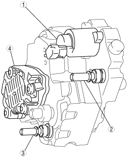
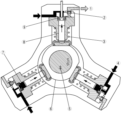
• The fuel pump is driven by the timing belt. The fuel transfer pump is driven by the fuel pump drive shaft.
• The fuel pump has three pumping elements with 120° offset (displacement pumps).
• The fuel metering valve is located in the supply duct between the fuel transfer pump and the fuel pump, and meters the quantity of fuel which is to be delivered into the high-pressure chamber in accordance with the current operating status of the engine.
• Any surplus fuel is returned to the fuel tank via the fuel return.
|
1
|
Fuel metering valve
|
|
2
|
Supply from the fuel filter
|
|
3
|
Fuel return
|
|
4
|
Fuel transfer pump
|
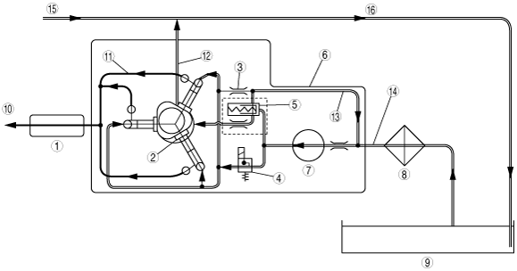
Flow of fuel through fuel pump
|
1
|
Common rail
|
|
2
|
High‐pressure range
|
|
3
|
Pressure restriction
|
|
4
|
Fuel metering valve
|
|
5
|
Overflow reducing valve
|
|
6
|
Fuel pump
|
|
7
|
Fuel transfer pump
|
|
8
|
Fuel filter
|
|
9
|
Fuel tank
|
|
10
|
To fuel injectors
|
|
11
|
High fuel pressure
|
|
12
|
Flow of fuel through fuel pump
|
|
13
|
Fuel return flow to fuel transfer pump
|
|
14
|
Fuel feed
|
|
15
|
Fuel injector leak‐off (fuel return)
|
|
16
|
Fuel return
|
Fuel Transfer Pump Operation
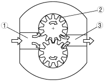
• The fuel transfer pump is designed as a gear pump and delivers the required fuel to the fuel pump.
Essential components are two counter‐rotating, meshed gear wheels that transport the fuel in the tooth gaps from the intake side to the pressure side.
The contact line of the gears forms a seal between the intake side and the pressure side and prevents the fuel from flowing back.
The delivery quantity is approximately proportional to engine speed. For this reason, fuel‐quantity control is required.
For fuel‐quantity control purposes, there is an overflow reducing valve incorporated in the fuel pump.
|
1
|
Intake side
|
|
2
|
Drive gear
|
|
3
|
High‐pressure side
|
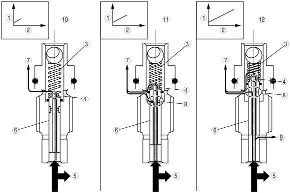
Overflow Reducing Valve Operation
• High‐pressure generation (up to
160 MPa {1,632 kgf/cm2, 23,206 psi}) means high thermal load on the individual components of the fuel pump. The mechanical components of the fuel pump must also be lubricated sufficiently to ensure durability.
The overflow reducing valve is designed to ensure optimum lubrication or cooling for all operating conditions.
At lower engine speeds (low transfer pump pressure) the control plunger is moved only slightly out of its seat. The lubrication/cooling requirement is correspondingly low.
A small amount of fuel is released to lubricate/cool the pump via the restriction at the end of the control plunger
The fuel pump features automatic venting. Any air in the fuel pump is vented through the restriction.
With increasing engine speed (increasing transfer pump pressure), the control plunger is moved further against the compression spring.
Increasing engine speeds require increased cooling of the fuel pump. Above a certain pressure, the fuel pump cooling bypass is opened and the flow rate through the fuel pump is increased.
At high engine speeds (high transfer pump pressure), the control plunger is moved further against the compression spring. The fuel pump cooling bypass is now fully open (maximum cooling).
Excess fuel is transferred via the return bypass to the intake side of the fuel transfer pump.
In this way, the internal pump pressure is limited to a maximum of 600 kPa {6.12 kgf/cm2, 87.0 psi}.
|
1
|
Transfer pump pressure
|
|
2
|
Time
|
|
3
|
Spring
|
|
4
|
Restriction
|
|
5
|
To high‐pressure chambers
|
|
6
|
Control plunger
|
|
7
|
Lubrication/cooling/ventilation ‐ fuel pump
|
|
8
|
Fuel pump cooling bypass
|
|
9
|
Return bypass to fuel transfer pump
|
|
10
|
Low engine speeds
|
|
11
|
Increasing engine speeds
|
|
12
|
High engine speeds
|
High Pressure Generation
• The fuel pump is driven via the drive shaft.
An eccentric element is fixed to the drive shaft and moves the three plungers up and down according to the cam lobes of the eccentric element.
Fuel pressure from the fuel transfer pump is applied to the inlet valve. If the transfer pressure exceeds the internal pressure of the high-pressure chamber (pump plunger in TDC position), the inlet valve opens.
Fuel is now pressed into the high‐pressure chamber, which moves the pump plunger downwards (intake stroke).
If BDC of the pump plunger is exceeded, the inlet valve closes due to the increasing pressure in the high‐pressure chamber. The fuel in the high‐pressure chamber can no longer escape.
As soon as the pressure in the high‐pressure chamber exceeds the pressure in the common rail, the outlet valve opens and the fuel is pressed into the common rail via the high‐pressure connection (delivery stroke).
The pump plunger delivers fuel until TDC is reached. After this, the pressure drops so that the outlet valve closes.
As the pressure on the remaining fuel is reduced, the pump plunger moves downward.
If the pressure in the high‐pressure chamber falls below the transfer pressure, the inlet valve reopens and the process starts again.
|
1
|
High‐pressure to common rail
|
|
2
|
Exhaust valve
|
|
3
|
Spring
|
|
4
|
Fuel feed
|
|
5
|
Drive shaft
|
|
6
|
Eccentric cam
|
|
7
|
High‐pressure chamber
|
|
8
|
Pump piston
|
|
9
|
Intake valve
|
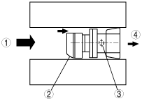
Zero Delivery Restriction Operation
•
The zero delivery restriction is located between the annular channel that is connected to the inlet valves of the high‐pressure chambers and the fuel metering valve.
Even in fully closed state, the fuel metering valve is not completely sealed. This means that a small leakage amount still enters the annular channel to the high‐pressure chambers by means of transfer pump pressure, which opens the inlet valves and can therefore lead to undesirable pressure increases in the high pressure system.
To prevent this, the zero delivery restriction features a calibrated bore. In this way, excess fuel is fed back to the intake side of the fuel transfer pump.
|
1
|
From high‐pressure chamber annular channel
|
|
2
|
Zero delivery restriction
|
|
3
|
Calibrated bore (φ0.4 mm {0.0157 in})
|
|
4
|
To fuel transfer pump
|