PRESILENCER, MAIN SILENCER REPLACEMENT[LF, L3]
id0115c2800800
-
Note
-
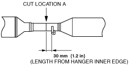
• The presilencer and main silencer are integrated with the TWC and tailpipe. Therefore, when replacing the presilencer and main silencer, cut between the TWC and presilencer, and between the main silencer and tailpipe.
Cut Location
1. Remove the rear tunnel member. (See EXHAUST SYSTEM REMOVAL/INSTALLATION[LF, L3].)
2. Remove the front tunnel member. (See EXHAUST SYSTEM REMOVAL/INSTALLATION[LF, L3].)
-
Caution
-
• Be careful not to deform the pipe when cutting. If the pipe is deformed, the new pipe may not be installed correctly.
3. Cut the pipe between the main silencer and tailpipe using the following procedure. (Cut location B)
-
Note
-
• Perform measurement parallel to the pipe being cut.
- (1) Measure the length from the hanger inner edge at the end.
-
- (2) Cut the pipe at the specified location.
-
-
Caution
-
• Be careful not to deform the pipe when cutting. If the pipe is deformed, the new pipe may not be installed correctly.
-
Note
-
• The pipe can be cut after removing it from the vehicle. In this case, replace the gasket with a new one.
4. Cut the pipe between the TWC and presilencer using the following procedure. (Cut location A)
- (1) Measure the length from the hanger end.
-
- (2) Cut the pipe at the specified location.
-
5. Remove burrs from the cut surface on both the TWC and tail pile side using a round file.
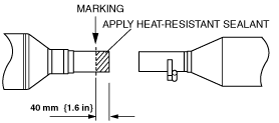
6. Install the new presilencer and main silencer to the TWC using the following procedure. (Cut location A)
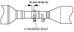
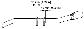
- (1) Measure the indicated length from the cut surface of the TWC and mark.
-
- (2) Apply heat-resistant sealant to the marked position along the complete perimeter.
-
- (3) If the pipe is cut after removing it from the vehicle, replace the gasket with a new one and install the TWC to the WU-TWC. (See EXHAUST SYSTEM REMOVAL/INSTALLATION[LF, L3].)
-
-
Note
-
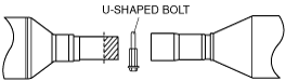
• The U-shaped bolt can be inserted to the pipe on either side.
- (4) Insert the U-shaped bolt.
-
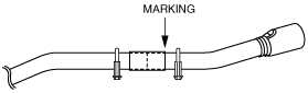
- (5) Insert the new presilencer to the TWC, and align the cut surface of the pipe with the marking.
-
- (6) Secure the exhaust pipe to the rubber hanger.
-
7. Install the new presilencer and main silencer to the tailpipe using the following procedure. (Cut location B)
- (1) Remove the tailpipe from the rubber hanger.
-
- (2) Measure the indicated length from the cut surface of the tailpipe and mark.
-
- (3) Apply heat-resistant sealant to the specified position along the complete perimeter.
-
- (4) Insert the U-shaped bolt.
-
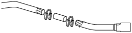
- (5) Insert the joint pipe to the main silencer.
-
- (6) Insert the tailpipe to the joint pipe.
-
- (7) Secure the exhaust pipe to the rubber hanger.
-
- (8) Align the cut surface of the joint pipe with the marking.
-
- (9) Verify that the exhaust pipe is installed without any bends or strain on the pipe.
-
8. Tighten the U-shaped bolt between the TWC and the new presilencer using the following procedure. (Cut location A)
-
Note
-
• The presilencer has a marked line at the specified position where the U-shaped bolt is to be set.
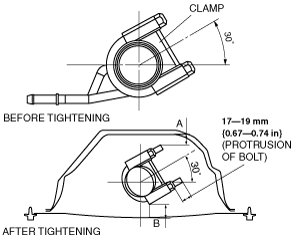
- (1) Set the U-shaped bolt in the specified position.
-
- (2) Set the U-shaped bolt so that the clearance between the bolt and surrounding parts is as indicated in the figure.
-
-
A: Clearance between the U-shaped bolt end and the vehicle side insulator
-
10 mm {0.40 in} or longer
-
B: Clearance between the U-shaped bolt and the tunnel member
-
20 mm {0.79 in} or longer
-
Caution
-
• Do not loosen U-shaped bolt after tightening. If it is loosened, the bolt cannot be tightened at the specified torque with the specified protrusion.
• Tighten the U-shaped bolt in three or four steps, left and right equally, to prevent clamp deformation.
- (3) Tighten the U-shaped bolt.
-
-
Protrusion of U-shaped bolt after tightening
-
17—19 mm {0.67—0.74 in}
9. Tighten the U-shaped bolt between the tailpipe and the new main silencer using the following procedure. (Cut location B)
-
Note
-
• The joint pipe has a marked line at the specified position where the U-shaped bolt is to be set.
- (1) Set the U-shaped bolt in the specified position.
-
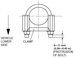
- (2) Set the U-shaped bolt so that it faces the vehicle lower side.
-
-
Caution
-
• Do not loosen U-shaped bolt after tightening. If it is loosened, the bolt cannot be tightened at the specified torque with the specified protrusion.
• Tighten the U-shaped bolt in three or four steps, left and right equally, to prevent clamp deformation.
-
Note
-
• Tighten the U-shaped bolt on the main silencer side first, then the tailpipe side.
- (3) Tighten the U-shaped bolt on the main silencer side.
-
-
Protrusion of U-shaped bolt after tightening
-
9—11 mm {0.36—0.43 in}
- (4) Gradually tighten the U-shaped bolt on the tailpipe side verifying that the tailpipe end is at the center of the bumper as viewed from behind the vehicle.
-
-
Protrusion of U-shaped bolt after tightening
-
9—11 mm {0.36—0.43 in}