|
am3zzw00001507
EXHAUST SYSTEM REMOVAL/INSTALLATION [MZ-CD 1.6 (Y6)]
id0115c3800200
1. Remove the battery cover. (See BATTERY REMOVAL/INSTALLATION [MZ-CD 1.6 (Y6)].)
2. Disconnect the negative battery cable.
3. Remove the engine cover.
4. Remove the under cover.
5. Remove the air hose between the turbocharger and air cleaner. (See INTAKE-AIR SYSTEM REMOVAL/INSTALLATION [MZ-CD 1.6 (Y6)].)
6. Remove the charge air cooler pipe (inlet) and air pipe. (See INTAKE-AIR SYSTEM REMOVAL/INSTALLATION [MZ-CD 1.6 (Y6)].)
7. Remove in the order indicated in the table.
8. Install in the reverse order of removal.
am3zzw00001507
|
|
1
|
Front tunnel member
|
|
2
|
Rear tunnel member
|
|
3
|
Main silencer
|
|
4
|
Exhaust manifold flexible pipe
|
|
5
|
Catalyst exhaust gas temperature sensor (High power-Euro 4)
|
|
6
|
Catalytic converter bracket
|
|
7
|
Catalytic converter insulator
|
|
8
|
Clamp
|
|
9
|
Catalytic converter
|
|
10
|
Oil pipe
|
|
11
|
Exhaust manifold insulator
|
|
12
|
Turbocharger
|
|
13
|
Exhaust manifold
|
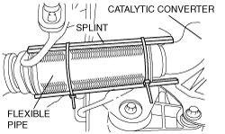
Exhaust Manifold Flexible Pipe Removal Note
1. Loosen the exhaust manifold insulator bolts.
2. Support the flexible pipe with a support wrap or splint as shown in the figure.
am3zzw00001508
|
3. Detach the exhaust flexible pipe from the catalytic converter.
4. Discard the gasket and nuts.
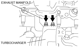
Exhaust Manifold Installation Note
1. Tighten the exhaust manifold installation nuts in the order shown in the figure.
am3zzw00001509
|
Turbocharger Replacement Note
Inspection for turbocharger replacement
1. Remove the oil pipe and the oil pipe installation bolts.
2. Verify that there is no blockage caused by particles in the oil pipe and on the oil pipe installation bolts.
3. Verify that there are no particles in the lubrication system.
4. Inspect the oil pressure. (See OIL PRESSURE INSPECTION [MZ-CD 1.6 (Y6)].)
5. After determining the reason for the turbocharger damage install a new turbocharger.
Turbocharger Installation Note
1. Set the new clamp and turbocharger in the engine.
2. Temporarily tighten the new turbocharger fixing nuts.
Upper nut
am3zzw00001510
|
Lower nut
am3zzw00001511
|
3. Temporarily tighten the clamp nut.
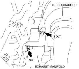
4. Temporarily tighten the turbocharger support bracket bolt and nut.
am3zzw00001512
|
5. Tighten the turbocharger fixing nuts.
6. Tighten the turbocharger support bracket bolt.
7. Tighten the turbocharger support bracket nut.
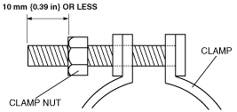
8. Loosen the clamp nut. When loosening the clamp nut, do not loosen the clamp nut excessively, and try to leave 10 mm {0.39 in} or less of thread.
am3zzw00001513
|
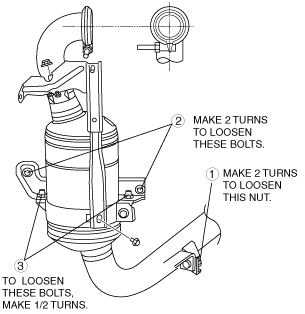
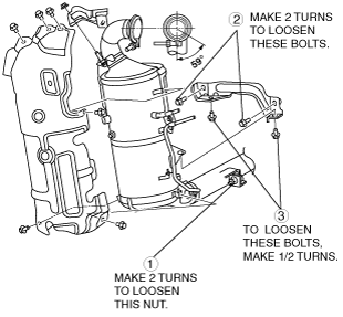
9. Loosen the catalytic converter fixing bolts and nut in the order shown in the figure.
Standard power-Euro 4
am3zzw00001514
|
High power-Euro 4
am3zzw00001515
|
10. Tighten the clamp nut.
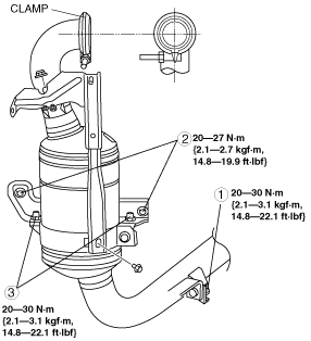
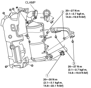
11. Tighten the catalytic converter fixing bolts and nut in the order shown in the figure.
Standard power-Euro 4
am3zzw00001516
|
High power-Euro 4
am3zzw00001517
|
Catalytic Converter and Clamp Installation Note
Standard power-Euro 4
1. Temporarily tighten catalytic converter fixing bolts A by hand until bracket A is attached.
am3zzw00001518
|
2. Set the new clamp to the pipe of the catalytic converter.
3. Install the catalytic converter by passing the hanger on the pipe of the catalytic converter through the bracket stud under the engine and temporarily tighten with the catalytic converter fixing bolts C.
4. Tighten the clamp nut B with the clamp stud pointing downwards from the level position.
5. Tighten the catalytic converter fixing nut D.
6. Tighten the catalytic converter fixing bolts C.
7. Tighten the catalytic converter fixing bolts A.
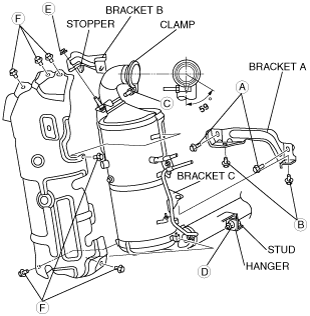
High power-Euro 4
1. Align to the bolt hole position as shown in the figure, and install the rear side of catalytic converter insulator to the catalytic converter, then tighten the bolts.
am3zzw00001519
|
2. Install bracket A to the engine and temporarily tighten with catalytic converter fixing bolts A.
am3zzw00001520
|
3. Set the new clamp to the pipe of the catalytic converter.
4. Set bracket C of the catalytic converter on bracket A, which is temporarily installed to the engine, and install the catalytic converter by passing the hanger on the pipe of the catalytic converter through the bracket stud under the engine.
5. Temporarily tighten the catalytic converter fixing bolts B until bracket A and bracket C are attached.
6. Tighten clamp nut C with the clamp stud pointing downwards from the level position.
7. Tighten the catalytic converter fixing nut D.
8. Tighten the catalytic converter fixing bolts A.
9. Tighten the catalytic converter fixing bolts B.
Catalytic Converter Insulator Installation Note
Standard power-Euro 4
1. Install bracket C and temporarily tighten nut E and bolt F.
am3zzw00001518
|
2. Tighten nut E.
3. Install the catalytic converter insulator and temporarily tighten bolts G.
am3zzw00001521
|
4. Tighten bolts G.
5. Tighten bolts F.
High power-Euro 4
1. Temporarily tighten nut E until the stopper of bracket B is completely engaged.
am3zzw00001520
|
2. Tighten nut E.
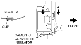
3. Secure the front and rear insulators with the clip as shown in the figure.
am3zzw00001522
|
4. Temporarily tighten bolts F.
5. Tighten bolts F.