 |
am3zzn00000824
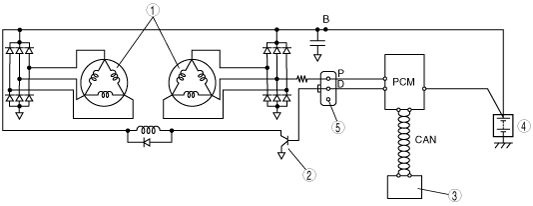
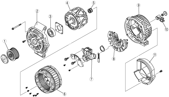
GENERATOR CONSTRUCTION[L3 Turbo]
id0117b2102300
am3zzn00000824
|
|
1
|
Pulley
|
|
2
|
Front cover
|
|
3
|
Front bearing
|
|
4
|
Rotor
|
|
5
|
Rear bearing
|
|
6
|
Stator coil
|
|
7
|
Regulator component (built-in power transistor)
|
|
8
|
Rectifier
|
|
9
|
Rear cover
|
|
10
|
Terminal B component
|
|
11
|
Heat insulator
|
am3zzn00000825
|
|
1
|
Stator coil
|
|
2
|
Power transistor
|
|
3
|
Instrument cluster (warning light)
|
|
4
|
Battery
|
|
5
|
Dummy
|
am3zzn00000826
|
|
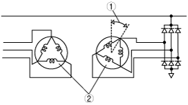
1
|
Phase difference
|
|
2
|
Stator coil
|
am3zzn00000827
|
|
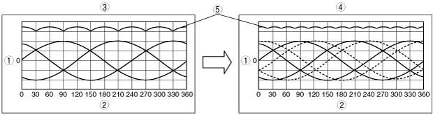
1
|
Voltage (V)
|
|
2
|
Angle (°)
|
|
3
|
Stator coil (includes 1 type)
|
|
4
|
Stator coil (includes 2 type)
|
|
5
|
Rectified voltage
|