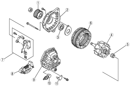
Without throttle valve actuator
am3zzn00000317
|
|
1
|
Pulley
|
|
2
|
Front cover
|
|
3
|
Front bearing
|
|
4
|
Rotor
|
|
5
|
Rear bearing
|
|
6
|
Stator
|
|
7
|
Regulator component (built-in power transistor)
|
|
8
|
Rectifier
|
|
9
|
Rear cover
|
|
10
|
Terminal B component
|
|
11
|
Bracket
|
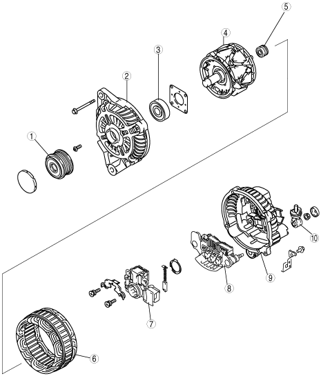
With throttle valve actuator
am3zzn00001342
|
|
1
|
Pulley
|
|
2
|
Front cover
|
|
3
|
Front bearing
|
|
4
|
Rotor
|
|
5
|
Rear bearing
|
|
6
|
Stator
|
|
7
|
Regulator component (built-in power transistor)
|
|
8
|
Rectifier
|
|
9
|
Rear cover
|
|
10
|
Terminal B component
|
|
11
|
Bracket
|
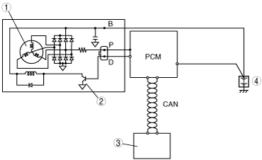
Without throttle valve actuator
am3zzn00000318
|
|
1
|
Stator coil
|
|
2
|
Power transistor
|
|
3
|
Instrument cluster (warning light)
|
|
4
|
Battery
|
With throttle valve actuator
am3zzn00001343
|

|
1
|
Stator coil
|
|
2
|
Power transistor
|
|
3
|
Instrument cluster (warning light)
|
|
4
|
Battery
|