 |
am3zzn00000216
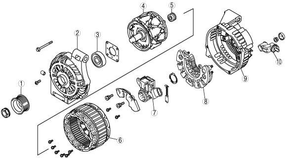
GENERATOR CONSTRUCTION[LF, L3]
id0117c2102300
European (L.H.D. U.K.) Specs.
am3zzn00000216
|
|
1
|
Pulley
|
|
2
|
Front cover
|
|
3
|
Front bearing
|
|
4
|
Rotor
|
|
5
|
Rear bearing
|
|
6
|
Stator coil
|
|
7
|
Regulator component (built-in power transistor)
|
|
8
|
Rectifier
|
|
9
|
Rear cover
|
|
10
|
Terminal B component
|
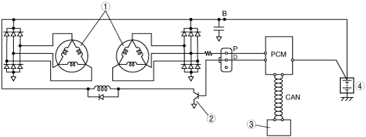
am3zzn00000217
|
|
1
|
Stator coil
|
|
2
|
Power transistor
|
|
3
|
Instrument cluster (warning light)
|
|
4
|
Battery
|
am3zzn00000218
|
|
1
|
Stator coil
|
|
2
|
Phase difference
|
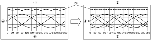
am3zzn00000219
|
|
1
|
Stator coil (Includes 1type)
|
|
2
|
Stator coil (Includes 2type)
|
|
3
|
Rectified voltage
|
|
4
|
Voltage (V)
|
|
5
|
Angle (°)
|
Except for European (L.H.D. U.K.) Specs.
am3zzn00001266
|
|
1
|
Pulley
|
|
2
|
Front cover
|
|
3
|
Front bearing
|
|
4
|
Rotor
|
|
5
|
Rear bearing
|
|
6
|
Stator coil
|
|
7
|
Regulator component (built-in power transistor)
|
|
8
|
Rectifier
|
|
9
|
Rear cover
|
|
10
|
Terminal B component
|
am3zzn00001267
|
|
1
|
Stator coil
|
|
2
|
Power transistor
|
|
3
|
Instrument cluster (warning light)
|
|
4
|
Battery
|