 |
am3zzw00001843
GENERATOR INSPECTION[LF, L3]
id0117c2800300
Generator Warning Light
1. Verify that the battery is fully charged.
2. Verify that the drive belt deflection/tension is correct. (See DRIVE BELT INSPECTION[LF, L3].)
3. With the ignition switch at ON, verify that the generator warning light illuminates.
4. Verify that the generator warning light goes off after the engine is started.
Generator
Voltage
1. Verify that the battery is fully charged.
2. Verify that the drive belt deflection/tension is correct. (See DRIVE BELT INSPECTION[LF, L3].)
3. Turn off all electrical loads.
4. Start the engine and verify that the generator rotates smoothly without any noise while the engine is running.
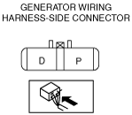
5. Measure the voltage at each terminal using a tester.
European (L.H.D. U.K.) specs.
am3zzw00001843
|
Except for European (L.H.D. U.K.) specs.
am3zzw00003217
|
Current
1. Verify that the battery is fully charged.
2. Verify that the drive belt deflection/tension is correct. (See DRIVE BELT INSPECTION[LF, L3].)
3. Remove the battery cover. (See BATTERY REMOVAL/INSTALLATION[LF, L3].)
4. Disconnect the negative battery cable.
5. Connect a tester capable of reading 120 A or more between generator terminal B and the wiring harness.
6. Connect the negative battery cable.
7. Turn off all electrical loads.
8. Start the engine.
9. Increase engine speed to 2,500 rpm.
10. Turn the following electrical loads on and verify that the current reading increases more than the minimum value indicated below.
PCM and generator shearing inspection
1. Inspect as follows:
|
Step |
Inspection |
Action |
||
|---|---|---|---|---|
|
1
|
Measure the generator terminal B voltage when the electrical loads*1 are on and off.
|
15 V or more
|
Go to Step 2.
|
|
|
13—15 V
|
Normal*2
|
|||
|
13 V or less
|
Go to Step 3.
|
|||
|
2
|
Monitor the ALTT V PID using M-MDS, or measure the voltage of PCM terminal 2AJ*3, 2AM*4 using a tester. Is the voltage between 13 and 15 V ?
|
Yes
|
Go to Step 4.
|
|
|
No
|
PCM input error.
|
|||
|
3
|
Monitor the ALTT V PID using M-MDS, or measure the voltage of PCM terminal 2AJ*3, 2AM*4 using a tester. Is the voltage between 13 and 15 V ?
|
Yes
|
Go to Step 5.
|
|
|
No
|
PCM input error.
|
|||
|
4
|
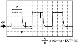
Monitor the ALTF PID using M-MDS, or calculate the duty value of the PCM terminal 2AI*3, 2AQ*4 using oscilloscope. Is the duty value 100% ?
|
 |
Yes
|
PCM input error.
|
|
No
|
PCM, generator, or both are not normal.
|
|||
|
5
|
Monitor the ALTF PID using M-MDS, or calculate the duty value of the PCM terminal 2AI*3, 2AQ*4 using oscilloscope. Is the duty value 0% ?
|
|
Yes
|
PCM input error.
|
|
No
|
PCM, generator, or both are not normal.
|
|||
Generator Inner Parts (European (L.H.D. U.K.) specs.)
Rotor
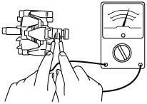
1. Measure the resistance between the slip rings using a tester.
am3zzw00000173
|
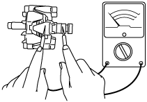
2. Verify that there is no continuity between the slip ring and core using a tester.
am3zzw00000174
|
3. Inspect the slip ring surface condition.
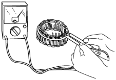
Stator coil
1. Verify that the continuity is as indicated in the table.
am3zzw00000175
|
am3zzw00000182
|
2. Verify that there is no continuity between the stator coil leads and core using a tester.
am3zzw00000177
|
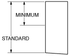
Brush
1. Inspect brushes for wear.
am3zzw00000183
|
Brush spring
1. Measure the force of the brush spring using a spring pressure gauge.
2. Read the spring pressure gauge at the brush tip projection of 2 mm {0.079 in}.
am3zzw00000179
|
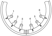
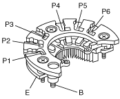
Rectifier (Using an analog circuit tester)
1. Inspect for continuity of the diodes using an analog circuit tester.
am3zzw00000180
|
Specification
|
Negative |
Positive |
Continuity |
|---|---|---|
|
E
|
P1, P2, P3, P4, P5, P6
|
Yes
|
|
B
|
No
|
|
|
P1, P2, P3, P4, P5, P6
|
E
|
No
|
|
B
|
Yes
|
Rectifier (Using a digital circuit tester)
1. Inspect for continuity of the diodes using a digital circuit tester.
Specification
|
Negative |
Positive |
Continuity |
|---|---|---|
|
E
|
P1, P2, P3, P4, P5, P6
|
No
|
|
B
|
Yes
|
|
|
P1, P2, P3, P4, P5, P6
|
E
|
Yes
|
|
B
|
No
|
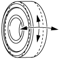
Bearing
1. Inspect for abnormal noise, looseness, and sticking.
am3zzw00000181
|
Generator Inner Parts (Except for European (L.H.D. U.K.) specs.)
Rotor
1. Measure the resistance between the slip rings using a tester.
am3zzw00003218
|
2. Verify that there is no continuity between the slip ring and core using a tester.
am3zzw00003219
|
3. Inspect the slip ring surface condition.
Stator coil
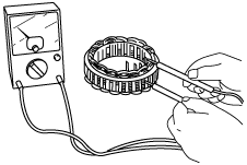
1. Inspect for continuity between the stator coil leads using a tester.
am3zzw00003220
|
2. Verify that there is no continuity between the stator coil leads and the core using a tester.
am3zzw00003221
|
Brush
1. Inspect brushes for wear.
am3zzw00003222
|
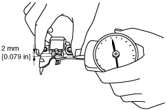
Brush spring
1. Measure the force of the brush spring using a spring pressure gauge.
2. Read the spring pressure gauge at the brush tip projection of 2 mm {0.079 in}.
am3zzw00003223
|
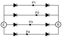
Rectifier
1. Inspect for continuity of the diodes using a tester.
chu0117w011
|
chu0117w013
|
Specification
|
Tester |
Continuity |
|
|---|---|---|
|
Negative |
Positive |
|
|
E
|
P1, P2, P3, P4
|
Yes
|
|
B
|
No
|
|
|
P1, P2, P3, P4
|
E
|
No
|
|
B
|
Yes
|
|
Bearing
1. Inspect for abnormal noise, looseness, and sticking.
am3zzw00003224
|