 |
am3zzn00001728
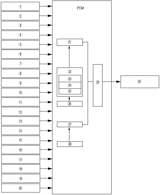
FUEL INJECTION CONTROL BLOCK DIAGRAM [LF, L3]
id0140a9101800
am3zzn00001728
|
|
1
|
IAT sensor
|
|
2
|
MAF sensor
|
|
3
|
TP sensor
|
|
4
|
MAP sensor
|
|
5
|
CMP sensor
|
|
6
|
CKP sensor
|
|
7
|
ECT sensor
|
|
8
|
A/F sensor
|
|
9
|
HO2S
|
|
10
|
Neutral switch (MTX)
|
|
11
|
CPP switch (MTX)
|
|
12
|
TR switch (ATX)
|
|
13
|
Brake switch
|
|
14
|
A/C switch
|
|
15
|
Refrigerant pressure switch
|
|
16
|
Battery voltage
|
|
17
|
Generator terminal P
|
|
18
|
Vehicle speed signal (CAN)
|
|
19
|
BARO sensor
|
|
20
|
Instrument cluster
|
|
21
|
Synchronized fuel injection
|
|
22
|
Effective injection time
|
|
23
|
Injection time at engine start
|
|
24
|
Basic injection time
|
|
25
|
Various correction types
|
|
26
|
Ineffective injection time
|
|
27
|
Non-synchronized injection control
|
|
28
|
Ineffective injection time
|
|
29
|
Fuel injector energization timing and energization time
|
|
30
|
Fuel injector
|