am3zzn00000918
|
|
1
|
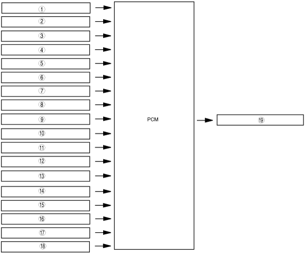
Neutral switch (MTX)
|
|
2
|
CPP switch (MTX)
|
|
3
|
MAF sensor
|
|
4
|
IAT sensor
|
|
5
|
TP sensor
|
|
6
|
APP sensor
|
|
7
|
MAP sensor
|
|
8
|
CKP sensor
|
|
9
|
ECT sensor
|
|
10
|
Brake switch
|
|
11
|
TR switch (ATX)
|
|
12
|
A/C on request signal
|
|
13
|
Ignition switch
|
|
14
|
Vehicle speed signal
|
|
15
|
Refrigerant pressure switch (low-pressure switch, high-pressure switch)
|
|
16
|
Refrigerant pressure switch (middle switch)
|
|
17
|
Generator (Terminal P: stator coil)
|
|
18
|
BARO sensor
|
|
19
|
Throttle valve actuator
|