am3zzn00001371
|
|
1
|
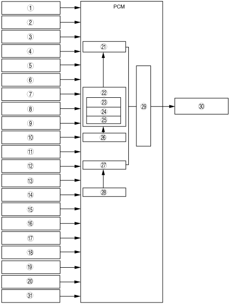
Neutral switch (MTX)
|
|
2
|
CPP switch (MTX)
|
|
3
|
PSP switch (Without throttle valve actuator)
|
|
4
|
ECT sensor
|
|
5
|
IAT sensor
|
|
6
|
CKP sensor
|
|
7
|
CMP sensor
|
|
8
|
TP sensor
|
|
9
|
MAF sensor
|
|
10
|
Front HO2S
|
|
11
|
Rear HO2S
|
|
12
|
Vehicle speed signal
|
|
13
|
TR switch (ATX)
|
|
14
|
Brake switch
|
|
15
|
A/C on request signal
|
|
16
|
Refrigerant pressure switch (low pressure switch, high pressure switch)
|
|
17
|
Battery
|
|
18
|
Engine stop request signal (Without throttle valve actuator)
|
|
19
|
APP sensor (With throttle valve actuator)
|
|
20
|
MAP sensor (With throttle valve actuator)
|
|
21
|
Synchronized fuel injection
|
|
22
|
Effective injection time
|
|
23
|
Injection time at engine start
|
|
24
|
Basic injection time
|
|
25
|
Corrections
|
|
26
|
Ineffective injection time
|
|
27
|
Non-synchronized fuel injection
|
|
28
|
Ineffective injection time
|
|
29
|
Fuel injector actuation timing and actuation time
|
|
30
|
Fuel injector
|
|
31
|
BARO sensor (If equipped)
|