am3zzn00000366
|
|
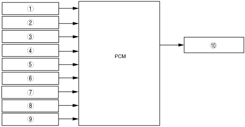
1
|
ECT sensor
|
|
2
|
PCM temperature sensor (Without throttle valve actuator)
|
|
3
|
TP sensor
|
|
4
|
Vehicle speed signal
|
|
5
|
A/C on request signal
|
|
6
|
Refrigerant pressure switch (low pressure switch, high pressure switch)
|
|
7
|
Refrigerant pressure switch (medium pressure switch)
|
|
8
|
Battery
|
|
9
|
APP sensor (With throttle valve actuator)
|
|
10
|
Fan control module
|