 |
am3zzn00000369
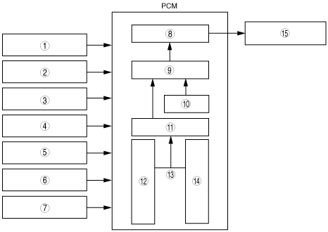
GENERATOR CONTROL BLOCK DIAGRAM[ZJ, ZY, Z6]
id0140b1172400
am3zzn00000369
|
|
1
|
ECT sensor
|
|
2
|
IAT sensor
|
|
3
|
CKP sensor
|
|
4
|
Vehicle speed signal
|
|
5
|
Generator (Terminal P: stator coil)
|
|
6
|
Battery
|
|
7
|
Current sensor (With throttle valve actuator)
|
|
8
|
Field coil excitation time
|
|
9
|
Target excitation current
|
|
10
|
Generator rotation speed
|
|
11
|
Target generated current
|
|
12
|
Target battery voltage (regulating voltage)
|
|
13
|
Deviation
|
|
14
|
Current battery voltage
|
|
15
|
Generator (Terminal D: field coil)
|