am3zzn00000358
|
|
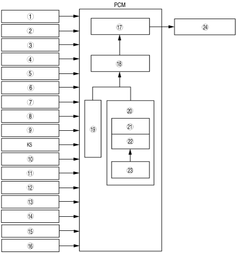
1
|
Neutral switch (MTX)
|
|
2
|
CPP switch (MTX)
|
|
3
|
PSP switch (Without throttle valve actuator)
|
|
4
|
ECT sensor
|
|
5
|
IAT sensor
|
|
6
|
CKP sensor
|
|
7
|
CMP sensor
|
|
8
|
TP sensor
|
|
9
|
MAF sensor
|
|
10
|
TR switch (ATX)
|
|
11
|
Brake switch
|
|
12
|
A/C on request signal
|
|
13
|
Refrigerant pressure switch (low pressure switch, high pressure switch)
|
|
14
|
Engine stop request signal (Without throttle valve actuator)
|
|
15
|
Variable tumble shutter valve switch (With throttle valve actuator)
|
|
16
|
APP sensor (With throttle valve actuator)
|
|
17
|
Igniter operation time
|
|
18
|
Ignition timing
|
|
19
|
Fixed ignition
|
|
20
|
Cycle estimated ignition
|
|
21
|
Idle spark advance
|
|
22
|
Basic spark advance
|
|
23
|
Corrections
|
|
24
|
Ignition coil
|