 |
am3zzw00000238
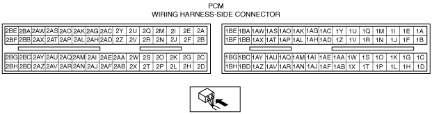
PCM INSPECTION [ZJ, ZY, Z6]
id0140b1802500
Not Using the M-MDS (Without Throttle Valve Actuator)
PCM terminal voltage table (Reference)
am3zzw00000238
|
Terminal voltage table (Reference)
|
Terminal |
Signal name |
Connected to |
Measurement condition |
Voltage (V) |
Inspection item(s) |
|
|---|---|---|---|---|---|---|
|
1A
|
—
|
—
|
—
|
—
|
—
|
|
|
1B
|
—
|
—
|
—
|
—
|
—
|
|
|
1C
|
—
|
—
|
—
|
—
|
—
|
|
|
1D
|
—
|
—
|
—
|
—
|
—
|
|
|
1E
|
—
|
—
|
—
|
—
|
—
|
|
|
1F
|
—
|
—
|
—
|
—
|
—
|
|
|
1G*1
|
Internal ground
|
Input/turbine speed sensor shield wire
|
Under any condition
|
1.0 or less
|
• Related wiring harness
|
|
|
1H
|
—
|
—
|
—
|
—
|
—
|
|
|
1I
|
—
|
—
|
—
|
—
|
—
|
|
|
1J
|
—
|
—
|
—
|
—
|
—
|
|
|
1K*1
|
Input/turbine speed sensor (–)
|
Input/turbine speed sensor
|
• Input/turbine speed sensor
• Related wiring harness
|
|||
|
1L
|
—
|
—
|
—
|
—
|
—
|
|
|
1M
|
—
|
—
|
—
|
—
|
—
|
|
|
1N
|
—
|
—
|
—
|
—
|
—
|
|
|
1O*1
|
Input/turbine speed sensor (+)
|
Input/turbine speed sensor
|
• Input/turbine speed sensor
• Related wiring harness
|
|||
|
1P
|
*3CPP switch
|
CPP switch
|
Ignition switch is turned to the ON position.
|
Clutch pedal depressed
|
1.0 or less
|
• CPP switch
• Related wiring harness
|
|
Clutch pedal released
|
B+
|
|||||
|
*1Manual up
|
Up switch
|
Ignition switch is turned to the ON position.
|
Detects up-shift operation of selector lever in M range
|
1.0 or less
|
• Selector lever
• Related wiring harness
|
|
|
Others
|
B+
|
|||||
|
1Q
|
Refrigerant pressure (low, high)
|
Refrigerant pressure switch (low pressure switch, high pressure switch)
|
Refrigerant pressure is more than the specification or less than the specification. (Refrigerant pressure switch (low pressure switch, high pressure switch) is off.)
|
B+
|
• Refrigerant pressure switch (low pressure switch, high pressure switch)
• Related wiring harness
|
|
|
Others
|
1.0 or less
|
|||||
|
1R
|
—
|
—
|
—
|
—
|
—
|
|
|
1S
|
CAN_L
|
Instrument cluster, ABS HU/CM, DSC HU/CM, DLC-2
|
Because this terminal is for CAN, good/no good judgment by terminal voltage is not possible.
|
—
|
||
|
1T
|
—
|
—
|
—
|
—
|
—
|
|
|
1U
|
Refrigerant pressure (middle)
|
Refrigerant pressure switch (middle)
|
Idle
|
Refrigerant pressure is more than the specification. (Refrigerant pressure switch (middle) is on.)
|
1.0 or less
|
• Refrigerant pressure switch (middle)
• Related wiring harness
|
|
Refrigerant pressure is less than the specification. (Refrigerant pressure switch (middle) is off.)
|
B+
|
|||||
|
1V
|
Brake switch
|
Brake switch
|
Brake pedal depressed
|
B+
|
• Brake switch
• Related wiring harness
|
|
|
Brake pedal released
|
1.0 or less
|
|||||
|
1W
|
CAN_H
|
Instrument cluster, ABS HU/CM, DSC HU/CM, DLC-2
|
Because this terminal is for CAN, good/no good judgment by terminal voltage is not possible.
|
—
|
||
|
1X*1
|
Selector lever position
|
TR switch
|
Ignition switch is turned to the ON position.
|
P position
|
Approx. 4.6
|
• TR switch
• Related wiring harness
|
|
R position
|
Approx. 3.9
|
|||||
|
N position
|
Approx. 3.2
|
|||||
|
D range
|
Approx. 2.5
|
|||||
|
M range
|
Approx. 2.5
|
|||||
|
1Y
|
—
|
—
|
—
|
—
|
—
|
|
|
1Z
|
—
|
—
|
—
|
—
|
—
|
|
|
1AA*3, *9
|
Vehicle speed (–)
|
VSS
|
Under any condition
|
Below 1.0
|
• VSS
• Related wiring harness
|
|
|
1AB
|
*3Neutral switch
|
Neutral switch
|
Ignition switch is turned to the ON position.
|
Neutral
|
1.0 or less
|
• Neutral switch
• Related wiring harness
|
|
Except above
|
B+
|
|||||
|
*1Manual down
|
Down switch
|
Ignition switch is turned to the ON position.
|
Detects down-shift operation of selector lever in M range
|
1.0 or less
|
• Selector lever
• Related wiring harness
|
|
|
Others
|
B+
|
|||||
|
1AC*7
|
Fuel pump control
|
Fuel pump relay
|
Immediately after ignition switch is turned to the ON position.
|
1.0 or less
|
• Fuel pump relay
• Related wiring harness
|
|
|
Ignition switch is turned to the ON position.
|
B+
|
|||||
|
Cranking
|
1.0 or less
|
|||||
|
Idle
|
||||||
|
1AD
|
—
|
—
|
—
|
—
|
—
|
|
|
1AE*3, *9
|
Vehicle speed (+)
|
VSS
|
• VSS
• Related wiring harness
|
|||
|
1AF*1
|
Pressure control solenoid (+)
|
Pressure control solenoid
|
• Pressure control solenoid
• Related wiring harness
|
|||
|
1AG
|
—
|
—
|
—
|
—
|
—
|
|
|
1AH*8
|
Fuel pump control
|
Fuel pump relay
|
Immediately after ignition switch is turned to the ON position.
|
1.0 or less
|
• Fuel pump relay
• Related wiring harness
|
|
|
1AI
|
—
|
—
|
—
|
—
|
—
|
|
|
1AJ*1
|
Shift solenoid D
|
Shift solenoid D
|
P or N position
|
B+
|
• Shift solenoid D
• Related wiring harness
|
|
|
Except above
|
1.0 or less
|
|||||
|
1AK*7
|
Starter relay control
|
Starter relay
|
Cranking
|
1.0 or less
|
• Starter relay
• Related wiring harness
|
|
|
1AL
|
The A/C cut-off control.
|
A/C relay
|
The A/C is operating.
|
1.0 or less
|
• A/C relay
• Related wiring harness
|
|
|
The A/C is not operating.
|
B+
|
|||||
|
1AM
|
—
|
—
|
—
|
—
|
—
|
|
|
1AN*1
|
Internal ground
|
TFT sensor, TR switch
|
Under any condition
|
1.0 or less
|
• Related wiring harness
|
|
|
1AO
|
—
|
—
|
—
|
—
|
—
|
|
|
1AP
|
Fan control
|
Fan control module
|
Test mode is on.*2
|
CTP
|
B+
|
• Fan control module
• Related wiring harness
|
|
WOT
|
1.0 or less
|
|||||
|
1AQ*1
|
M range switch
|
M range switch
|
Ignition switch is turned to the ON position.
|
M range
|
1.0 or less
|
• Selector lever
• Related wiring harness
|
|
Except above
|
B+
|
|||||
|
1AR*1
|
Shift solenoid E
|
Shift solenoid E
|
During TCC operation
|
B+
|
• Shift solenoid E
• Related wiring harness
|
|
|
Except above
|
1.0 or less
|
|||||
|
1AS
|
—
|
—
|
—
|
—
|
—
|
|
|
1AT
|
Vehicle speed (–)
|
VSS
|
Under any condition
|
Below 1.0
|
• VSS
• Related wiring harness
|
|
|
1AU*1
|
ATF temperature
|
TFT sensor
|
Ignition switch is turned to the ON position.
|
TFT is 20 °C {68 °F}
|
Approx. 3.3
|
• TFT sensor
• Related wiring harness
|
|
TFT is 40 °C {104 °F}
|
Approx. 2.4
|
|||||
|
TFT is 60 °C {140 °F}
|
Approx. 1.5
|
|||||
|
1AV*1
|
Pressure control solenoid (–)
|
Pressure control solenoid
|
• Pressure control solenoid
• Related wiring harness
|
|||
|
1AW
|
Main relay
|
Main relay
|
Ignition switch is off.
|
1.0 or less
|
• Main relay
• Related wiring harness
|
|
|
Ignition switch is turned to the ON position.
|
||||||
|
1AX
|
Back-up power supply
|
Battery
|
Under any condition
|
B+
|
• Battery
• Related wiring harness
|
|
|
1AY*1
|
Vehicle speed
|
VSS
|
• VSS
• Related wiring harness
|
|||
|
1AZ*1
|
Shift solenoid A
|
Shift solenoid A
|
• Shift solenoid A
• Related wiring harness
|
|||
|
1BA
|
—
|
—
|
—
|
—
|
—
|
|
|
1BB
|
Battery voltage
|
Main relay
|
Ignition switch is off.
|
1.0 or less
|
• Main relay
• Battery
• Related wiring harness
|
|
|
Ignition switch is turned to the ON position.
|
B+
|
|||||
|
1BC*1
|
VSS power supply
|
VSS
|
Ignition switch is turned to the ON position.
|
B+
|
• Related wiring harness
|
|
|
1BD*1
|
Shift solenoid C
|
Shift solenoid C
|
• Shift solenoid C
• Related wiring harness
|
|||
|
1BE
|
Ignition switch
|
Ignition switch
|
Ignition switch is off.
|
1.0 or less
|
• Ignition switch
• Related wiring harness
|
|
|
Ignition switch is turned to the ON position.
|
B+
|
|||||
|
1BF
|
Battery voltage
|
Main relay
|
Ignition switch is off
|
1.0 or less
|
• Main relay
• Battery
• Related wiring harness
|
|
|
Ignition switch is turned to the ON position.
|
B+
|
|||||
|
1BG*1
|
Battery voltage
|
Main relay
|
Ignition switch is off.
|
1.0 or less
|
• Main relay
• Battery
• Related wiring harness
|
|
|
Ignition switch is turned to the ON position.
|
B+
|
|||||
|
1BH*1
|
Shift solenoid B
|
Shift solenoid B
|
• Shift solenoid B
• Related wiring harness
|
|||
|
2A
|
Ignition coil power supply
|
Ignition coil
|
Ignition switch is turned to the ON position.
|
B+
|
• Related wiring harness
|
|
|
2B
|
Fuel injection control
|
Fuel injector No.1
|
• Fuel injector No.1
• Related wiring harness
|
|||
|
2C
|
Fuel injection control
|
Fuel injector No.2
|
• Fuel injector No.2
• Related wiring harness
|
|||
|
2D
|
Fuel injection control
|
Fuel injector No.3
|
• Fuel injector No.3
• Related wiring harness
|
|||
|
2E
|
Fuel injector No.1 power supply
|
Fuel injector No.1
|
Ignition switch is turned to the ON position.
|
B+
|
• Related wiring harness
|
|
|
2F
|
Fuel injector No.2 power supply
|
Fuel injector No.2
|
Ignition switch is turned to the ON position.
|
B+
|
• Related wiring harness
|
|
|
2G
|
Fuel injector No.3 power supply
|
Fuel injector No.3
|
Ignition switch is turned to the ON position.
|
B+
|
• Related wiring harness
|
|
|
2H
|
Fuel injection control
|
Fuel injector No.4
|
• Fuel injector No.4
• Related wiring harness
|
|||
|
2I
|
—
|
—
|
—
|
—
|
—
|
|
|
2J
|
ECT
|
ECT sensor
|
Ignition switch is turned to the ON position.
|
ECT is 20 °C {68 °F}
|
Approx. 3.0
|
• ECT sensor
• Related wiring harness
|
|
ECT is 60 °C {140 °F}
|
Approx. 1.4
|
|||||
|
ECT is 80 °C {176 °F}
|
Approx. 0.9
|
|||||
|
2K
|
Rear HO2S
|
Rear HO2S
|
Idle
|
Alternates between 0 and 1.0
|
• Rear HO2S
• Related wiring harness
|
|
|
2L
|
Fuel injector No.4 power supply
|
Fuel injector No.4
|
Ignition switch is turned to the ON position.
|
B+
|
• Related wiring harness
|
|
|
2M
|
ESA control
|
Ignition coil No.4
|
• Ignition coil No.4
• Related wiring harness
|
|||
|
2N
|
—
|
—
|
—
|
—
|
—
|
|
|
2O
|
—
|
—
|
—
|
—
|
—
|
|
|
2P
|
CKP
|
CKP sensor
|
• CKP sensor
• Related wiring harness
|
|||
|
2Q
|
ESA control
|
Ignition coil No.3
|
• Ignition coil No.3
• Related wiring harness
|
|||
|
2R
|
—
|
—
|
—
|
—
|
—
|
|
|
2S*10
|
BARO sensor
|
BARO sensor
|
Ignition switch is turned to the ON position.
|
Altitude: 0—2,500 m
|
1.8—2.8
|
• BARO sensor
• Related wiring harness
|
|
2T
|
Input/output device power supply
|
CKP sensor, CMP sensor, front HO2S, rear HO2S, purge solenoid valve, OCV
|
Ignition switch is turned to the ON position.
|
B+
|
• Related wiring harness
|
|
|
2U
|
ESA control
|
Ignition coil No.2
|
• Ignition coil No.2
• Related wiring harness
|
|||
|
2V
|
—
|
—
|
—
|
—
|
—
|
|
|
2W
|
Constant voltage (vref)
|
TP sensor
|
Ignition switch is turned to the ON position.
|
Approx. 5.0
|
• TP sensor
• Related wiring harness
|
|
|
2X
|
IAC (+)
|
IAC valve
|
Idle
|
B+
|
• IAC valve
• Related wiring harness
|
|
|
2Y
|
ESA control
|
Ignition coil No.1
|
• Ignition coil No.1
• Related wiring harness
|
|||
|
2Z
|
—
|
—
|
—
|
—
|
—
|
|
|
2AA
|
TP
|
TP sensor
|
Ignition switch is turned to the ON position.
|
CTP
|
0.3—1.0
|
• TP sensor
• Related wiring harness
|
|
WOT
|
3.1—4.5
|
|||||
|
2AB
|
IAC (–)
|
IAC valve
|
• IAC valve
• Related wiring harness
|
|||
|
2AC
|
PSP switch
|
PSP switch
|
Idle
|
Steering wheel at straight ahead position
|
B+
|
• PSP switch
• Related wiring harness
|
|
While turning steering wheel
|
1.0 or less
|
|||||
|
2AD
|
—
|
—
|
—
|
—
|
—
|
|
|
2AE
|
Internal ground
|
TP sensor
|
Under any condition
|
1.0 or less
|
• Related wiring harness
|
|
|
2AF
|
Variable tumble control (open)
|
Variable tumble shutter valve actuator
|
The engine is hot.
|
When the ignition switch turned to the ON position.
|
B+*5
|
• Variable tumble shutter valve actuator
• Related wiring harness
|
|
Idle after cold start
|
When the ECT reaches 60 °C {140 °F}
|
|||||
|
Except above
|
1.0 or less
|
|||||
|
2AG
|
Variable valve timing control
|
OCV
|
Under any condition (See Inspection Using An Oscilloscope (Reference) (Without Throttle Valve Actuator).)
|
• OCV
• Related wiring harness
|
||
|
2AH
|
—
|
—
|
—
|
—
|
—
|
|
|
2AI
|
Front HO2S
|
Front HO2S
|
• Front HO2S
• Related wiring harness
|
|||
|
2AJ
|
Variable tumble control (close)
|
Variable tumble shutter valve actuator
|
The engine is cold.
|
When the ignition switch turned to the ON position.
|
B+*5
|
• Variable tumble shutter valve actuator
• Related wiring harness
|
|
Except above
|
1.0 or less
|
|||||
|
2AK
|
—
|
—
|
—
|
—
|
—
|
|
|
2AL
|
—
|
—
|
—
|
—
|
—
|
|
|
2AM
|
Front HO2S heater control
|
Front HO2S heater
|
• Front HO2S
• Related wiring harness
|
|||
|
2AN
|
Generator control
|
Generator (terminal D)
|
• Generator
• Related wiring harness
|
|||
|
2AO*6
|
Variable intake air control (open)
|
Variable intake air shutter valve actuator
|
When the ignition switch turned to the ON position.
|
1.0 or less
|
• Variable intake air shutter valve actuator
• Related wiring harness
|
|
|
When the engine speed is increased gradually and reaches 4,100 rpm.
|
B+*5
|
|||||
|
Except above
|
1.0 or less
|
|||||
|
2AP
|
—
|
—
|
—
|
—
|
—
|
|
|
2AQ
|
IAT
|
IAT sensor
|
Ignition switch is turned to the ON position.
|
IAT is 20 °C {68 °F}
|
Approx. 2.2
|
• IAT sensor
• Related wiring harness
|
|
IAT is 30 °C {86 °F}
|
Approx. 1.8
|
|||||
|
2AR
|
Generator output voltage
|
Generator (terminal P)
|
• Generator
• Related wiring harness
|
|||
|
2AS*6
|
Variable intake air control (close)
|
Variable intake air shutter valve actuator
|
When the ignition switch is turned to the ON position.
|
B+*5
|
• Variable intake air shutter valve actuator
• Related wiring harness
|
|
|
When the engine speed is decreased gradually and reaches 4,100 rpm.
|
||||||
|
Except above
|
1.0 or less
|
|||||
|
2AT
|
Rear HO2S
|
Rear HO2S
|
After fixed period of time from engine start
|
1.0 or less
|
• Rear HO2S
• Related wiring harness
|
|
|
Engine speed is 2,700 or more.
|
B+
|
|||||
|
2AU
|
MAF
|
MAF sensor
|
Ignition switch is turned to the ON position.
|
Approx. 0.7
|
• MAF sensor
• Related wiring harness
|
|
|
Idle
|
Approx. 1.3
|
|||||
|
2AV
|
Purge control
|
Purge solenoid valve
|
• Purge solenoid valve
• Related wiring harness
|
|||
|
2AW
|
—
|
—
|
—
|
—
|
—
|
|
|
2AX
|
Internal ground
|
ECT sensor, front HO2S, rear HO2S
|
Under any condition
|
1.0 or less
|
• Related wiring harness
|
|
|
2AY
|
Internal ground
|
IAT sensor
|
Under any condition
|
1.0 or less
|
• Related wiring harness
|
|
|
2AZ
|
Ground
|
Ground
|
Under any condition
|
1.0 or less
|
• Related wiring harness
|
|
|
2BA
|
Knocking
|
Knock sensor
|
Ignition switch is turned to the ON position. (Use digital type voltmeter, because measurement voltage will be detected less than true voltage when using analog type voltmeter)
|
Approx. 2.4
|
• Knock sensor
• Related wiring harness
|
|
|
2BB
|
CMP
|
CMP sensor
|
• CMP sensor
• Related wiring harness
|
|||
|
2BC
|
Internal ground
|
MAF sensor
|
Under any condition
|
1.0 or less
|
• Related wiring harness
|
|
|
2BD
|
Ground
|
Ground
|
Under any condition
|
1.0 or less
|
• Related wiring harness
|
|
|
2BE
|
Internal ground
|
HO2S shield wire
|
Under any condition
|
1.0 or less
|
• Related wiring harness
|
|
|
2BF
|
Internal ground
|
CKP sensor, CMP sensor
|
Under any condition
|
1.0 or less
|
• Related wiring harness
|
|
|
2BG
|
Power supply
|
MAF sensor
|
Under any condition
|
B+
|
• Related wiring harness
|
|
|
2BH
|
Ground
|
Ground
|
Under any condition
|
1.0 or less
|
• Related wiring harness
|
|
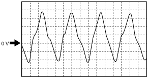
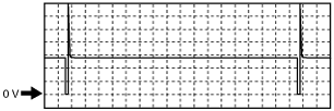
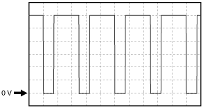
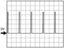
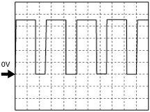
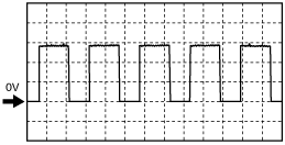
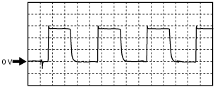
Inspection Using An Oscilloscope (Reference) (Without Throttle Valve Actuator)
Input/turbine speed sensor (–) signal
am3zzw00000239
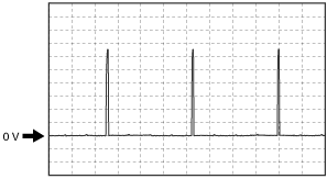
|
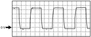
Input/turbine speed sensor (+) signal
am3zzw00000240
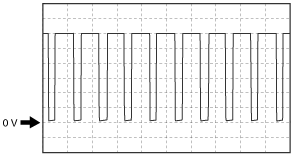
|
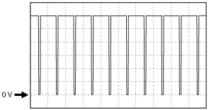
Vehicle speed signal (MTX)
am3zzw00003414
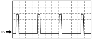
|
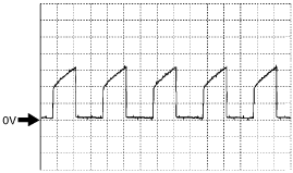
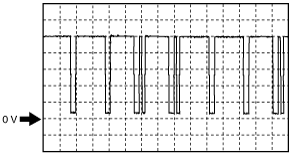
Pressure control solenoid (+) signal
am3zzw00000241
|
Pressure control solenoid (–) signal
am3zzw00000242
|
Vehicle speed signal (ATX)
am3zzw00000243
|
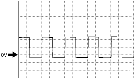
Shift solenoid A signal
am3zzw00000244
|
Shift solenoid C signal
am3zzw00000245
|
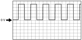
Shift solenoid B signal
am3zzw00000246
|
Fuel injection control signal
am3zzw00000247
|
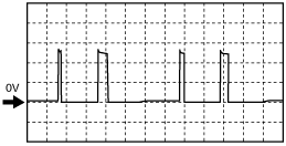
ESA control signal
am3zzw00000248
|
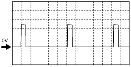
CKP signal
am3zzw00000249
|
IAC (–) signal
am3zzw00000251
|
Variable valve timing control signal
am3zzw00000252
|
Oxygen concentration signal
am3zzw00000253
|
HO2S heater signal
am3zzw00000254
|
Generator control signal
am3zzw00000255
|
Generator output voltage signal
am3zzw00000256
|
Purge control signal
am3zzw00000257
|
CMP signal
am3zzw00000258
|
Not Using the M-MDS (With Throttle Valve Actuator)
PCM terminal voltage table (Reference)
am3zzw00000238
|
|
Terminal |
Signal name |
Connected to |
Test condition |
Voltage (V) |
Inspection item |
|
|---|---|---|---|---|---|---|
|
1A
|
Ground
|
Input/turbine speed sensor shield wire*1
|
Under any condition
|
Below 1.0
|
• Related wiring harness
|
|
|
Body ground*3
|
||||||
|
1B
|
—
|
—
|
—
|
—
|
—
|
|
|
1C
|
Ground
|
APP sensor
|
Under any condition
|
Below 1.0
|
• Related wiring harness
|
|
|
1D*1
|
Shift solenoid A
|
Shift solenoid A
|
• Shift solenoid A
• Related wiring harness
|
|||
|
1E
|
APP sensor power supply
|
APP sensor
|
Under any condition
|
Approx. 5.0
|
• Related wiring harness
|
|
|
1F
|
—
|
—
|
—
|
—
|
—
|
|
|
1G
|
Brake switch
|
Brake switch
|
Brake pedal depressed
|
B+
|
• Brake switch
• Related wiring harness
|
|
|
Brake pedal released
|
Below 1.0
|
|||||
|
1H*1
|
Shift solenoid B
|
Shift solenoid B
|
• Shift solenoid B
• Related wiring harness
|
|||
|
1I
|
—
|
—
|
—
|
—
|
—
|
|
|
1J
|
Neutral switch*3
|
Neutral switch
|
Ignition switch is turned to the ON position.
|
Neutral
|
Below 1.0
|
• Neutral switch
• Related wiring harness
|
|
Except above
|
B+
|
|||||
|
Manual down*1
|
Down switch
|
Ignition switch is turned to the ON position.
|
Detects down-shift operation of selector lever in M range.
|
Below 1.0
|
• Selector lever
• Related wiring harness
|
|
|
Except above
|
B+
|
|||||
|
1K*1
|
Shift solenoid D
|
Shift solenoid D
|
Idle
|
P, N position
D (4GR),
M (1GR, 4GR)
range
|
B+
|
• Shift solenoid D
• Related wiring harness
|
|
Except above
|
Below 1.0
|
|||||
|
1L*1
|
Shift solenoid C
|
Shift solenoid C
|
• Shift solenoid C
• Related wiring harness
|
|||
|
1M
|
CPP switch*3
|
CPP switch
|
Ignition switch is turned to the ON position.
|
Clutch pedal is depressed
|
Below 1.0
|
• CPP switch
• Related wiring harness
|
|
Clutch pedal is released
|
B+
|
|||||
|
Manual up*1
|
Up switch
|
Ignition switch is turned to the ON position.
|
Detects up-shift operation of selector lever in M range
|
Below 1.0
|
• Selector lever
• Related wiring harness
|
|
|
Except above
|
B+
|
|||||
|
1N*1
|
M range switch
|
M range switch
|
Ignition switch is turned to the ON position.
|
M range
|
Below 1.0
|
• Selector lever
• Related wiring harness
|
|
Except above
|
B+
|
|||||
|
1O*1
|
Shift solenoid E
|
Shift solenoid E
|
During TCC operation
|
B+
|
• Shift solenoid E
• Related wiring harness
|
|
|
Except above
|
Below 1.0
|
|||||
|
1P*1
|
Pressure control solenoid (+)
|
Pressure control solenoid
|
• Pressure control solenoid
• Related wiring harness
|
|||
|
1Q
|
APP sensor No.2
|
APP sensor
|
• APP sensor
• Related wiring harness
|
|||
|
1R*1
|
Input/turbine speed sensor (+)
|
Input/turbine speed sensor
|
• Input/turbine speed sensor
• Related wiring harness
|
|||
|
1S
|
—
|
—
|
—
|
—
|
—
|
|
|
1T*1
|
Pressure control solenoid (–)
|
Pressure control solenoid
|
• Pressure control solenoid
• Related wiring harness
|
|||
|
1U
|
—
|
—
|
—
|
—
|
—
|
|
|
1V*1
|
Input/turbine speed sensor (–)
|
Input/turbine speed sensor
|
• Input/turbine speed sensor
• Related wiring harness
|
|||
|
1W
|
—
|
—
|
—
|
—
|
—
|
|
|
1X*5
|
Starter relay
|
Starter relay
|
Cranking
|
Below 1.0
|
• Starter relay
• Related wiring harness
|
|
|
1Y
|
A/C
|
Refrigerant pressure switch (high, low), A/C amplifier
|
Refrigerant pressure is more than the specification or less than the specification. (Refrigerant pressure switch (high, low) is off.)
|
Approx. 5.0
|
• Refrigerant pressure switch (high, low)
• A/C amplifier
• Related wiring harness
|
|
|
Except above
|
Below 1.0
|
|||||
|
1Z
|
—
|
—
|
—
|
—
|
—
|
|
|
1AA
|
—
|
—
|
—
|
—
|
—
|
|
|
1AB
|
—
|
—
|
—
|
—
|
—
|
|
|
1AC
|
Refrigerant pressure switch (middle)
|
Refrigerant pressure switch (middle)
|
Refrigerant pressure is more than the specification. (Refrigerant pressure switch (middle) is on.)
|
Below 1.0
|
• Refrigerant pressure switch (middle)
• Related wiring harness
|
|
|
Refrigerant pressure is less than the specification. (Refrigerant pressure switch (middle) is off.)
|
B+
|
|||||
|
1AD
|
APP sensor No.1
|
APP sensor
|
Ignition switch is turned to the ON position.
|
Accelerator pedal depressed
|
Approx. 3.0
|
• APP sensor
• Related wiring harness
|
|
Accelerator pedal released
|
Approx. 0.4
|
|||||
|
1AE
|
CAN_H
|
CAN system related module, DLC-2
|
Because this terminal is for CAN, no valid determination of terminal voltage is possible.
|
• Related wiring harness
|
||
|
1AF
|
—
|
—
|
—
|
—
|
—
|
|
|
1AG
|
Ground
|
Current sensor, TFT sensor, TR switch
|
Under any condition
|
Below 1.0
|
• Related wiring harness
|
|
|
1AH*1
|
ATF temperature
|
TFT sensor
|
Ignition switch is turned to the ON position.
|
ATF temperature is 20 °C {68 °F}
|
Approx. 3.3
|
• TFT sensor
• Related wiring harness
|
|
ATF temperature is 40 °C {104 °F}
|
Approx. 2.4
|
|||||
|
ATF temperature is 60 °C {140 °F}
|
Approx. 1.5
|
|||||
|
1AI
|
CAN_L
|
CAN system related module, DLC-2
|
Because this terminal is for CAN, no valid determination of terminal voltage is possible.
|
• Related wiring harness
|
||
|
1AJ
|
Main relay
|
Main relay
|
Ignition switch off and a certain period has elapsed.
|
B+
|
• Main relay
• Related wiring harness
|
|
|
Ignition switch is turned to the ON position.
|
Below 1.0
|
|||||
|
1AK
|
Current sensor power supply
|
Current sensor
|
Under any condition
|
Approx. 5.0
|
• Related wiring harness
|
|
|
1AL
|
Current sensor
|
Current sensor
|
Ignition switch is turned to the ON position.
|
0.5—4.5
|
• Current sensor
• Related wiring harness
|
|
|
1AM
|
Fan control
|
Fan control module
|
Test mode is on.*2
|
CTP
|
B+
|
• Fan control module
• Related wiring harness
|
|
WOT
|
Below 1.0
|
|||||
|
1AN
|
A/C cut-off control
|
A/C relay
|
A/C operating
|
Below 1.0
|
• A/C relay
• Related wiring harness
|
|
|
A/C not operating
|
B+
|
|||||
|
1AO
|
—
|
—
|
—
|
—
|
—
|
|
|
1AP*3, *7
|
Vehicle speed (+)
|
VSS
|
• VSS
• Related wiring harness
|
|||
|
1AQ*5
|
Fuel pump control
|
Fuel pump relay
|
Ignition switch is turned to the ON position and a certain period has elapsed.
|
B+
|
• Fuel pump relay
• Related wiring harness
|
|
|
Cranking
|
Below 1.0
|
|||||
|
Idle
|
||||||
|
1AR*6
|
Fuel pump control
|
Fuel pump relay
|
Ignition switch is turned to the ON position and a certain period has elapsed.
|
B+
|
• Fuel pump relay
• Related wiring harness
|
|
|
Cranking
|
Below 1.0
|
|||||
|
Idle
|
||||||
|
1AS*1
|
Selector lever position
|
TR switch
|
Ignition switch is turned to the ON position.
|
P position
|
Approx. 4.6
|
• TR switch
• Related wiring harness
|
|
R range
|
Approx. 3.9
|
|||||
|
N position
|
Approx. 3.2
|
|||||
|
D range
|
Approx. 2.5
|
|||||
|
M range
|
Approx. 2.5
|
|||||
|
1AT*3, *7
|
Vehicle speed (–)
|
VSS
|
Under any condition
|
Below 1.0
|
• VSS
• Related wiring harness
|
|
|
1AU
|
—
|
—
|
—
|
—
|
—
|
|
|
1AV
|
—
|
—
|
—
|
—
|
—
|
|
|
1AW
|
—
|
—
|
—
|
—
|
—
|
|
|
1AX*1
|
Vehicle speed
|
VSS
|
• VSS
• Related wiring harness
|
|||
|
1AY
|
—
|
—
|
—
|
—
|
—
|
|
|
1AZ
|
—
|
—
|
—
|
—
|
—
|
|
|
1BA
|
—
|
—
|
—
|
—
|
—
|
|
|
1BB
|
B+
|
Main relay
|
Ignition switch off.
|
Below 1.0
|
• Main relay
• Battery
• Related wiring harness
|
|
|
Ignition switch is turned to the ON position.
|
B+
|
|||||
|
1BC
|
Back-up power supply
|
Battery
|
Under any condition
|
B+
|
• Battery
• Related wiring harness
|
|
|
1BD
|
Drive-by-wire relay control
|
Drive-by-wire relay
|
Ignition switch off and a certain period has elapsed.
|
Below 1.0
|
• Drive-by-wire relay
• Related wiring harness
|
|
|
Ignition switch is turned to the ON position.
|
||||||
|
1BE
|
Drive-by-wire relay control
|
Drive-by-wire relay
|
Ignition switch off.
|
Below 1.0
|
• Drive-by-wire relay
• Related wiring harness
|
|
|
Ignition switch is turned to the ON position.
|
B+
|
|||||
|
1BF
|
B+
|
Main relay
|
Ignition switch off.
|
Below 1.0
|
• Main relay
• Battery
• Related wiring harness
|
|
|
Ignition switch is turned to the ON position.
|
B+
|
|||||
|
1BG*1
|
B+
|
Main relay
|
Ignition switch off.
|
Below 1.0
|
• Main relay
• Battery
• Related wiring harness
|
|
|
Ignition switch is turned to the ON position.
|
B+
|
|||||
|
1BH
|
Ignition switch
|
Ignition switch
|
Ignition switch off
|
Below 1.0
|
• Ignition switch
• Related wiring harness
|
|
|
Ignition switch is turned to the ON position.
|
B+
|
|||||
|
2A
|
Fuel injection control
|
Fuel injector No.1
|
• Fuel injector No.1
• Related wiring harness
|
|||
|
2B
|
Fuel injection control
|
Fuel injector No.2
|
• Fuel injector No.2
• Related wiring harness
|
|||
|
2C
|
Fuel injection control
|
Fuel injector No.3
|
• Fuel injector No.3
• Related wiring harness
|
|||
|
2D
|
Ignition coil power supply
|
Ignition coil
|
Ignition switch is turned to the ON position.
|
B+
|
• Related wiring harness
|
|
|
2E
|
Fuel injector No.1 power supply
|
Fuel injector No.1
|
Ignition switch is turned to the ON position.
|
B+
|
• Related wiring harness
|
|
|
2F
|
Fuel injector No.2 power supply
|
Fuel injector No.2
|
Ignition switch is turned to the ON position.
|
B+
|
• Related wiring harness
|
|
|
2G
|
Fuel injector No.3 power supply
|
Fuel injector No.3
|
Ignition switch is turned to the ON position.
|
B+
|
• Related wiring harness
|
|
|
2H
|
Fuel injection control
|
Fuel injector No.4
|
• Fuel injector No.4
• Related wiring harness
|
|||
|
2I
|
Power supply
|
CMP sensor, Purge solenoid valve, OCV, CKP sensor, Front HO2S, Rear HO2S
|
Ignition switch is turned to the ON position.
|
B+
|
• Related wiring harness
|
|
|
2J
|
Ground
|
ECT sensor, Rear HO2S, Variable tumble shutter valve switch, MAP sensor
|
Under any condition
|
Below 1.0
|
• Related wiring harness
|
|
|
2K
|
EGR control
|
EGR valve
|
Idle (EGR control operating)
|
Below 1.0
|
• EGR valve
• Related wiring harness
|
|
|
2L
|
Fuel injector No.4 power supply
|
Fuel injector No.4
|
Ignition switch is turned to the ON position.
|
B+
|
• Related wiring harness
|
|
|
2M
|
Ground
|
CMP sensor, CKP sensor
|
Under any condition
|
Below 1.0
|
• Related wiring harness
|
|
|
2N
|
CMP
|
CMP sensor
|
• CMP sensor
• Related wiring harness
|
|||
|
2O
|
EGR control
|
EGR valve
|
Idle (EGR control operating)
|
B+
|
• EGR valve
• Related wiring harness
|
|
|
2P
|
EGR control
|
EGR valve
|
Idle (EGR control operating)
|
B+
|
• EGR valve
• Related wiring harness
|
|
|
2Q
|
Ground
|
IAT sensor
|
Under any condition
|
Below 1.0
|
• Related wiring harness
|
|
|
2R
|
IAT
|
IAT sensor
|
Ignition switch is turned to the ON position.
|
IAT is 20 °C {68 °F}
|
Approx. 2.2
|
• IAT sensor
• Related wiring harness
|
|
IAT is 30 °C {86 °F}
|
Approx. 1.8
|
|||||
|
2S
|
Evaporative purge control
|
Purge solenoid valve
|
• Purge solenoid valve
• Related wiring harness
|
|||
|
2T
|
EGR control
|
EGR valve
|
Idle (EGR control operating)
|
B+
|
• EGR valve
• Related wiring harness
|
|
|
2U
|
Ground
|
MAF sensor
|
Under any condition
|
Below 1.0
|
• Related wiring harness
|
|
|
2V
|
MAF
|
MAF sensor
|
Ignition switch is turned to the ON position.
|
Approx. 0.7
|
• MAF sensor
• Related wiring harness
|
|
|
Idle
|
Approx. 1.3
|
|||||
|
2W
|
Variable valve timing control
|
OCV
|
• OCV
• Related wiring harness
|
|||
|
2X
|
Front HO2S heater control
|
Front HO2S (heater)
|
• Front HO2S
• Related wiring harness
|
|||
|
2Y
|
CKP
|
CKP sensor
|
• CKP sensor
• Related wiring harness
|
|||
|
2Z
|
Front HO2S
|
Front HO2S
|
Idle (after warm-up)
|
Approx. 2.8
|
• Front HO2S
• Related wiring harness
|
|
|
2AA
|
—
|
—
|
—
|
—
|
—
|
|
|
2AB
|
Rear HO2S heater control
|
Rear HO2S (heater)
|
• Rear HO2S
• Related wiring harness
|
|||
|
2AC
|
ECT
|
ECT sensor
|
Ignition switch is turned to the ON position.
|
ECT is 20 °C {68 °F}
|
Approx. 3.0
|
• ECT sensor
• Related wiring harness
|
|
ECT is 60 °C {140 °F}
|
Approx. 1.4
|
|||||
|
ECT is 80 °C {176 °F}
|
Approx. 0.9
|
|||||
|
2AD
|
Front HO2S
|
Front HO2S
|
Idle (after warm-up)
|
Approx. 2.4
|
• Front HO2S
• Related wiring harness
|
|
|
2AE
|
Generator output voltage
|
Generator (terminal P: stator coil)
|
• Generator
• Related wiring harness
|
|||
|
2AF
|
Generator field coil control
|
Generator (terminal D: field coil)
|
• Generator
• Related wiring harness
|
|||
|
2AG
|
Variable tumble control (open)
|
Variable tumble shutter valve actuator
|
The engine is hot.
|
Directly after the ignition switch is turned to the ON position.
|
B+*4
|
• Variable tumble shutter valve actuator
• Related wiring harness
|
|
Idle after cold start.
|
When the ECT is increased instant and reaches 60 °C {140 °F}
|
|||||
|
Except above
|
Below 1.0
|
|||||
|
2AH
|
Rear HO2S
|
Rear HO2S
|
Idle (after warm-up)
|
Alternates between 1.0 or less and B+
|
• Rear HO2S
• Related wiring harness
|
|
|
2AI
|
Variable intake air control (close)
|
Variable intake air shutter valve actuator
|
Directly after the ignition switch is turned to the ON position.
|
B+*4
|
• Variable intake air shutter valve actuator
• Related wiring harness
|
|
|
When the engine speed is decreased gradually and reaches 4,100 rpm.
|
||||||
|
Except above
|
Below 1.0
|
|||||
|
2AJ
|
Variable intake air control (open)
|
Variable intake air shutter valve actuator
|
Directly after the ignition switch is turned to the ON position.
|
Below 1.0
|
• Variable intake air shutter valve actuator
• Related wiring harness
|
|
|
When the engine speed is increased gradually and reaches 4,100 rpm.
|
B+*4
|
|||||
|
Except above
|
Below 1.0
|
|||||
|
2AK
|
Variable tumble control (close)
|
Variable tumble shutter valve actuator
|
The engine is cold.
|
Directly after the ignition switch is turned to the ON position.
|
B+*4
|
• Variable tumble shutter valve actuator
• Related wiring harness
|
|
Except above
|
Below 1.0
|
|||||
|
2AL
|
Variable tumble shutter valve switch
|
Variable tumble shutter valve switch
|
ECT is less than 60 °C {140 °F}
|
Engine speed is 3,250 rpm or less.
|
Approx. 3.6
|
• Variable tumble shutter valve switch
• Related wiring harness
|
|
other
|
Approx. 0.8
|
|||||
|
2AM
|
—
|
—
|
—
|
—
|
—
|
|
|
2AN
|
Knocking
|
KS
|
Ignition switch is turned to the ON position. (Use digital type voltmeter, because measurement voltage will be detected less than true voltage when using analog type voltmeter.)
|
Approx. 2.4
|
• KS
• Related wiring harness
|
|
|
2AO
|
Power supply
|
Variable tumble shutter valve switch, MAP sensor
|
Ignition switch is turned to the ON position.
|
Approx. 5.0
|
• Related wiring harness
|
|
|
2AP
|
MAP sensor
|
MAP sensor
|
Ignition switch is turned to the ON position.
|
Altitude: 0—2,500 m
|
1.8—2.8
|
• MAP sensor
• Related wiring harness
|
|
2AQ
|
ESA control
|
Ignition coil No.1
|
• Ignition coil No.1
• Related wiring harness
|
|||
|
2AR
|
ESA control
|
Ignition coil No.2
|
• Ignition coil No.2
• Related wiring harness
|
|||
|
2AS
|
TP sensor power supply
|
Throttle body (TP sensor)
|
Under any condition
|
Approx. 5.0
|
• Related wiring harness
|
|
|
2AT
|
TP sensor No.2
|
Throttle body (TP sensor)
|
Ignition switch is turned to the ON position.
|
Accelerator pedal depressed
|
Approx. 0.4
|
• TP sensor
• Related wiring harness
|
|
Accelerator pedal released
|
Approx. 4.5
|
|||||
|
2AU
|
ESA control
|
Ignition coil No.3
|
• Ignition coil No.3
• Related wiring harness
|
|||
|
2AV
|
ESA control
|
Ignition coil No.4
|
• Ignition coil No.4
• Related wiring harness
|
|||
|
2AW
|
TP sensor ground
|
Throttle body (TP sensor)
|
Under any condition
|
Below 1.0
|
• Related wiring harness
|
|
|
2AX
|
TP sensor No.1
|
Throttle body (TP sensor)
|
Ignition switch is turned to the ON position.
|
Accelerator pedal depressed
|
Approx. 4.6
|
• TP sensor
• Related wiring harness
|
|
Accelerator pedal released
|
Approx. 0.5
|
|||||
|
2AY
|
—
|
—
|
—
|
—
|
—
|
|
|
2AZ
|
Ground
|
Body ground
|
Under any condition
|
Below 1.0
|
• Related wiring harness
|
|
|
2BA
|
—
|
—
|
—
|
—
|
—
|
|
|
2BB
|
Ground
|
Body ground
|
Under any condition
|
Below 1.0
|
• Related wiring harness
|
|
|
2BC
|
Power supply
|
MAF sensor, EGR valve
|
Idle
|
B+
|
• Related wiring harness
|
|
|
2BD
|
Ground
|
Body ground
|
Under any condition
|
Below 1.0
|
• Related wiring harness
|
|
|
2BE
|
Throttle control (–)
|
Throttle body (throttle valve actuator)
|
• Throttle valve actuator
• Related wiring harness
|
|||
|
2BF
|
Throttle control (+)
|
Throttle body (throttle valve actuator)
|
• Throttle valve actuator
• Related wiring harness
|
|||
|
2BG
|
Ground
|
Front HO2S shield wire, Rear HO2S shield wire
|
Under any condition
|
Below 1.0
|
• Related wiring harness
|
|
|
2BH
|
Ground
|
Body ground
|
Under any condition
|
Below 1.0
|
• Related wiring harness
|
|
Inspection Using An Oscilloscope (Reference) (With Throttle Valve Actuator)
Shift solenoid A signal
am3zzw00000244
|
Shift solenoid B signal
am3zzw00000246
|
Shift solenoid C signal
am3zzw00000245
|
Pressure control solenoid (+) signal
am3zzw00000241
|
APP sensor No.2 signal
Accelerator pedal is released
c3u0140w016
|
Accelerator pedal is depressed
c3u0140w017
|
Input/turbine speed sensor (+) signal
am3zzw00000240
|
Pressure control solenoid (–) signal
am3zzw00000242
|
Input/turbine speed sensor (–) signal
am3zzw00000239
|
Vehicle speed signal (MTX)
am3zzw00003414
|
Vehicle speed signal (ATX)
am3zzw00000243
|
Fuel injection control signal
am3zzw00000247
|
CMP signal
am3zzw00000258
|
Evaporative purge control signal
am3zzw00000257
|
Variable valve timing control signal
am3zzw00000252
|
Front HO2S heater control signal
am3zzw00003415
|
CKP signal
am3zzw00000249
|
Rear HO2S heater control signal
am3zzw00003416
|
Generator output voltage signal
am3zzw00000256
|
Generator field coil control signal
am3zzw00003417
|
ESA control signal
am3zzw00000248
|
Throttle control (–) signal
am3zzw00003418
|
Throttle control (+) signal
am3zzw00003419
|
Using the M-MDS (Without Throttle Valve Actuator)
1. Connect the M-MDS to the DLC-2.
2. Turn the ignition switch to the ON position.
3. Measure the PID value.
|
Item (definition) |
Unit/Condition |
Condition/Specification (Reference) |
Inspection item(s) |
PCM terminal |
|||
|---|---|---|---|---|---|---|---|
|
AC_REQ
(Refrigerant pressure switch (low pressure switch, high pressure switch))
|
Off/On
|
• Refrigerant pressure is more than the specification or less than the specification. (Refrigerant pressure switch (low pressure switch, high pressure switch) is off.): Off
• Others: On
|
• Refrigerant pressure switch (low pressure switch, high pressure switch)
|
1Q
|
|||
|
ACCS
(A/C relay)
|
Off/On
|
• A/C is operating: On
• A/C is not operating: Off
|
• The following PIDs
|
1AL
|
|||
|
ALTF
(Generator field coil control duty value)
|
%
|
• Ignition switch is turned to the ON position: 0%
• Idling, E/L is operating: Duty value increases.
|
• The following PIDs
• Generator
|
2AN
|
|||
|
ALTT V
(Generator output voltage)
|
V
|
• Ignition switch is turned to the ON position: Approx. 1.0 V or less
• Idling (no electrical load): Approx. 14 V (This is an internal calculation value and differs from the terminal voltage.)
|
• Generator
|
2AR
|
|||
|
ARPMDES
(Target engine speed)
|
RPM
|
• Indicate the target engine speed
|
• The following PIDs
• IAC valve
|
—
|
|||
|
BARO*7
(Barometric pressure)
|
kPa, Bar, psi
|
• Ignition switch is turned to the ON position: Indicate the BARO
|
• BARO sensor
|
2S
|
|||
|
V
|
• Ignition switch is turned to the ON position
|
||||||
|
BOO
(Brake switch)
|
Off/On
|
• Brake pedal is depressed: On
• Brake pedal is released: Off
|
• Brake switch
|
1V
|
|||
|
CATT11_DSD
(Estimated catalytic converter temperature)
|
°C
|
°F
|
• Indicate the estimated catalytic converter temperature
|
• The following PIDs
|
—
|
||
|
CHRGLP
(Generator warning light)
|
Off/On
|
• Ignition switch is turned to the ON position: On
• Idling: Off
|
• Generator warning light
|
—
|
|||
|
COLP
(Refrigerant pressure switch (medium pressure switch))
|
OFF/ON
|
• Refrigerant pressure is more than the specification: ON
• Refrigerant pressure is less than the specification: OFF
|
• Refrigerant pressure switch (medium-pressure switch)
|
1U
|
|||
|
CPP*2
(Clutch pedal position)
|
Off/On
|
• Clutch pedal is depressed: On
• Clutch pedal is released: Off
|
• CPP switch
|
1P
|
|||
|
CPP/PNP*2
(Shift lever position)
|
Drive/Neutral
|
• Neutral: Neutral
• Other than neutral: Drive
|
• Neutral switch
|
1AB
|
|||
|
DTCCNT
(Number of DTC detected)
|
—
|
• Number of DTCs stored
|
—
|
—
|
|||
|
DWN SW*3
|
|||||||
|
ECT
(Engine coolant temperature)
|
°C
|
°F
|
• Ignition switch is turned to the ON position: Indicate the ECT
|
• ECT sensor
|
2J
|
||
|
V
|
• ECT is 20 °C {68 °F}: Approx. 3.0 V
• ECT is 60 °C {140 °F}: Approx. 1.4 V
• ECT is 80 °C {176 °F}: Approx. 0.9 V
|
||||||
|
EQ_RAT11_DSD
(Target lambda)
|
—
|
• Idling after warm-up: Approx.1
|
• Front HO2S
|
—
|
|||
|
EVAPCP
(Purge solenoid valve duty value)
|
%
|
• Ignition switch is turned to the ON position: 0 %
• Increase the engine speed: Duty value rises
|
• The following PIDs
|
2AV
|
|||
|
FAN_DUTY
(Fan control duty value)
|
%
|
• When all of following condition are met: 90 %
|
• The following PIDs
|
—
|
|||
|
FP
(Fuel pump relay)
|
Off/On
|
• Immediately after ignition switch is turned to the ON position: On
• Ignition switch is turned to the ON position: Off
• Idling: On
• Cranking: On
|
• Fuel pump relay
|
1AC*8
1AH*9
|
|||
|
FUELPW
(Fuel injector duration)
|
sec
|
• Idling: Approx. 2.0 ms
|
• The following PIDs
|
2B, 2C, 2D, 2H
|
|||
|
FUELSYS
(Fuel system status)
|
OL/CL/
OL-Drive/
OL-Fault/
CL-Fault
|
• Idling after warm-up: CL
|
• The following PIDs
|
—
|
|||
|
GEAR*3
|
|||||||
|
GENVDSD
(Target generator voltage)
|
V
|
• Indicate the target generator voltage
|
• The following PIDs
• Generator
|
—
|
|||
|
HTM_CNT*3
|
|||||||
|
HTM_DIS*3
|
|||||||
|
HTR11
(Front HO2S heater control)
|
Off/On
|
• Ignition switch is turned to the ON position: Off
• When the vehicle is driving at engine speed less than 4,300 rpm: On
|
• The following PIDs
|
2AM
|
|||
|
HTR12
(Rear HO2S heater control)
|
Off/On
|
• After fixed period of time from engine start: On
• Engine speed is 2,700 or more: Off
|
• The following PIDs
|
2AT
|
|||
|
IAC
(IAC duty value)
|
%
|
• Ignition switch is turned to the ON position: 0 %
• Idling (ECT is 88 °C {190 °F}, no load condition): Approx. 25 %
|
• The following PIDs
|
2X, 2AB
|
|||
|
IAT
(Intake air temperature)
|
°C
|
°F
|
• Ignition switch is turned to the ON position: Indicate the IAT
|
• IAT sensor
|
2AQ
|
||
|
V
|
• IAT is 20°C {68°F}: Approx. 2.2 V
• IAT is 30°C {86°F}: Approx. 1.8 V
|
||||||
|
IMRC
(Variable tumble control)
|
%
|
• Cold start and 3,250 rpm or less: 12.5—50
• Hot start or 3,250 rpm or more: 12.5—42
|
• The following PIDs
|
2AF, 2AJ
|
|||
|
Off/On
|
• Cold start and 3,250 rpm or less: On
• Hot start or 3,250 rpm or more: Off
|
||||||
|
IMTV*6
(Variable intake air control)
|
%
|
• Engine speed is less than 4,100 rpm: 12.5—50
• Engine speed is 4,100 rpm or more: 12.5—42
|
• The following PIDs
|
2AO, 2AS
|
|||
|
Off/On
|
• Engine speed is less than 4,100 rpm: On
• Engine speed is 4,100 rpm or more: Off
|
||||||
|
INGEAR
(Gears are engaged.)
|
Off/On
|
MTX
• When the following conditions are satisfied: On
• Except above: Off
|
• CPP switch
• Neutral switch
|
1P, 1AB
|
|||
|
ATX
• Driving range: On
• Except above: Off
|
• TR switch
|
—
|
|||||
|
IVS
(CTP condition)
|
Idle/Off Idle
|
• Idling: Idle
• Other than idling: Off Idle
|
• The following PIDs
|
—
|
|||
|
KNOCKR
(Knocking retard)
|
°
|
• Ignition switch is turned to the ON position: 0 °
• Idling: 0 °
|
• KS
|
2BA
|
|||
|
LINEDES*3
|
|||||||
|
LOAD
(Engine load)
|
%
|
• Idling (after warm-up): Approx. 23 %
|
• The following PIDs
|
—
|
|||
|
LONGFT1
(Long term fuel trim)
|
%
|
• Idling (after warm-up): Approx. –15—+15 %
|
• The following PIDs
|
—
|
|||
|
LPS*3
|
|||||||
|
MAF
(Mass air flow)
|
g/sec
|
• Ignition switch is turned to the ON position: Approx. 0 g/s
• Idling: Approx. 2.7 g/s
|
• MAF sensor
|
2AU
|
|||
|
V
|
• Ignition switch is turned to the ON position: Approx. 0.7 V
• Idling: Approx. 1.3 V
|
||||||
|
MIL
(Malfunction indicator lamp)
|
Off/On
|
• Ignition switch is turned to the ON position: On
• Idling: Off
(If there is a malfunction in emission control related system: On)
|
• MIL
|
—
|
|||
|
MIL_DIS
(Travelled distance since MIL illuminated)
|
km
|
mile
|
Indicate the travelled distance since the MIL illuminated
|
||||
|
MNL SW*3
|
|||||||
|
O2S11
(Front HO2S)
|
V
|
• Ignition switch is turned to the ON position: 1.0 V or less
• Idling (after warm-up): Alternates between 0 and 1.0 V
|
• Front HO2S
|
2AI
|
|||
|
O2S12
(Rear HO2S)
|
V
|
• Idling (after warm-up): Alternates between 0 and 1.0 V
|
• Rear HO2S
|
2K
|
|||
|
OSS*3
|
|||||||
|
PCM_T
(PCM temperature sensor)
|
V
|
• Ignition switch is turned to the ON position: Indicate the PCM temperature sensor output voltage
|
• PCM
|
—
|
|||
|
PCM_T_Max
(Maximum PCM temperature)
|
V
|
• Ignition switch is turned to the ON position: Indicate the maximum PCM temperature sensor output voltage
|
• PCM
|
—
|
|||
|
PSP
(PSP switch)
|
Low/High
|
• Steering wheel is in straight ahead position: Low
• Steering wheel is fully turned: High
|
• PSP switch
|
2AC
|
|||
|
RO2FT1
(Rear oxygen sensor fuel trim)
|
—
|
• Idling after warm-up: Approx. –0.03—+0.03
|
• The following PID
|
2K
|
|||
|
RPM
(Engine speed)
|
RPM
|
• Indicate the engine speed
|
• CKP sensor
|
2P
|
|||
|
SELTESTDTC
|
—
|
• Display the stored DTC by performing KOEO/KOER self-test
|
|||||
|
SHRTFT1
(Short term fuel trim (front))
|
%
|
• Idling (after warm-up): –25—+25%
|
• The following PIDs
|
—
|
|||
|
SHRTFT11
(Short term fuel trim (front))
|
%
|
• Idling (after warm-up): –25—+25%
|
• The following PIDs
|
2AI
|
|||
|
SHRTFT12
(Short term fuel trim (rear))
|
%
|
• Idling after warm-up: Approx. 99 %
|
• The following PIDs
|
2K
|
|||
|
SPARKADV
(Ignition timing)
|
°
|
• Indicate the ignition timing
|
• The following PIDs
|
2BB
|
|||
|
SSA/SS1*3
|
|||||||
|
SSB/SS2*3
|
|||||||
|
SSC/SS3*3
|
|||||||
|
SSD/SS4*3
|
|||||||
|
SSE/SS5*3
|
|||||||
|
test
(Test mode)
|
Off/On
|
• During test mode: On
• Other than test mode: Off
|
—
|
—
|
|||
|
TFT*3
|
|||||||
|
TFTV*3
|
|||||||
|
THOP*3
|
|||||||
|
TIRESIZE
(Tire revolution per mile)
|
rev/mile
|
• Indicate the tire revolution per a mile
|
|||||
|
TP
(TP)
|
%
|
• CTP: Approx. 12 %
• WOT: Approx. 75 %
|
• TP sensor
|
2AA
|
|||
|
V
|
• CTP: 0.3―1.0 V
• WOT: 3.1―4.5 V
|
||||||
|
TP REL
(Throttle position signal (relative value))
|
%
|
• CTP: Approx. 0 %
• WOT: Approx. 100 %
|
• TP sensor
|
2AA
|
|||
|
TPCT
(TP sensor voltage at CTP)
|
V
|
• 0.3―1.0 V
|
• TP sensor
|
2AA
|
|||
|
TR*3
|
|||||||
|
TR_SENS*3
|
|||||||
|
TSS*3
|
|||||||
|
UP SW*3
|
|||||||
|
VPWR
(Battery positive voltage)
|
V
|
• Ignition switch is turned to the ON position.: B+
• Idling: B+
|
• Battery
• Main relay
|
1AX, 1BB, 1BF
|
|||
|
1BG*3
|
|||||||
|
Vref
(Constant voltage)
|
V
|
• Ignition switch is turned to the ON position.: Approx. 5 V
|
• Battery
|
2W
|
|||
|
VSS
(Vehicle speed)
|
KPH
|
MPH
|
• Vehicle running: Indicate the vehicle speed
|
• VSS
|
*21AE
|
||
|
*31AY
|
|||||||
|
*10—
|
|||||||
|
VT ACT1
(Actual valve timing)
|
°
|
• Idling: 0 °
• Racing: 0―25 °
|
• The following PIDs
• OCV
|
2AG
|
|||
|
VT DIFF1
(Difference between target valve timing and actual valve timing)
|
°
|
• Idling: 0 °
|
• The following PIDs
• OCV
|
—
|
|||
|
VT DUTY1
(OCV control)
|
%
|
• Idling: Approx. 10 %
|
• The following PIDs
|
2AG
|
|||
Using the M-MDS (With Throttle Valve Actuator)
1. Connect the M-MDS to the DLC-2.
2. Turn the ignition switch to the ON position.
3. Measure the PID value.
|
Item (definition) |
Unit/Condition |
Condition/Specification (Reference) |
Inspection item(s) |
PCM terminal |
|||
|---|---|---|---|---|---|---|---|
|
AC_REQ
(Refrigerant pressure switch (low pressure switch, high pressure switch))
|
Off/On
|
• Refrigerant pressure is more than the specification or less than the specification. (Refrigerant pressure switch (low pressure switch, high pressure switch) is off.): Off
• Others: On
|
• Refrigerant pressure switch (low pressure switch, high pressure switch)
|
1Y
|
|||
|
ACCS
(A/C relay)
|
Off/On
|
• A/C is operating: On
• A/C is not operating: Off
|
• The following PIDs
|
1AN
|
|||
|
AFR
(Air/fuel ratio)
|
—
|
• Air/fuel ratio is displayed
|
• Rear HO2S
|
2AH
|
|||
|
AFR_ACT
(Actual air/fuel ratio)
|
—
|
• Actual air/fuel ratio is displayed
|
• Rear HO2S
|
2AH
|
|||
|
ALT_CUR_S
(Generator current sensor)
|
A
|
• Ignition switch is turned to the ON position: –100—100 A
• Increase in electrical load: Decreases
|
• Current sensor
|
1AL
|
|||
|
V
|
• Ignition switch is turned to the ON position: 0.5—4.5 V
• Decreases in electrical load: Increases
|
||||||
|
ALTF
(Generator field coil control duty value)
|
%
|
• Ignition switch is turned to the ON position: 0%
• Idling, E/L is operating: Duty value increases.
|
• The following PIDs
• Generator
|
2AF
|
|||
|
ALTT V
(Generator output voltage)
|
V
|
• Ignition switch is turned to the ON position: Approx. 1.0 V or less
• Idling (no electrical load): Approx. 14 V (This is an internal calculation value and differs from the terminal voltage.)
|
• Generator
|
2AE
|
|||
|
APP
(Accelerator pedal position)
|
%
|
• Accelerator pedal released: 0 %
• Accelerator pedal depressed: 100 %
|
• The following PIDs
|
1Q, 1AD
|
|||
|
APP1
(Accelerator pedal position sensor 1)
|
%
|
• Accelerator pedal released: Approx. 15 %
• Accelerator pedal depressed: Approx. 60 %
|
• APP sensor
|
1AD
|
|||
|
V
|
• Accelerator pedal released: Approx. 0.4 V
• Accelerator pedal depressed: Approx. 3.0 V
|
||||||
|
APP2
(Accelerator pedal position sensor 2)
|
%
|
• Accelerator pedal released: Approx. 8 %
• Accelerator pedal depressed: Approx. 60 %
|
• APP sensor
|
1Q
|
|||
|
V
|
• Accelerator pedal released: Approx. 0.4 V
• Accelerator pedal depressed: Approx. 3.0 V
|
||||||
|
ARPMDES
(Target engine speed)
|
RPM
|
• Indicate the target engine speed
|
• The following PIDs
• IAC valve
|
—
|
|||
|
BOO
(Brake switch)
|
Off/On
|
• Brake pedal is depressed: On
• Brake pedal is released: Off
|
• Brake switch
|
1G
|
|||
|
CHRGLP
(Generator warning light)
|
Off/On
|
• Ignition switch is turned to the ON position: On
• Idling: Off
|
• Generator warning light
|
—
|
|||
|
COLP
(Refrigerant pressure switch (medium pressure switch))
|
OFF/ON
|
• Refrigerant pressure is more than the specification: ON
• Refrigerant pressure is less than the specification: OFF
|
• Refrigerant pressure switch (medium-pressure switch)
|
1AC
|
|||
|
CPP*1
(Clutch pedal position)
|
Off/On
|
• Clutch pedal is depressed: On
• Clutch pedal is released: Off
|
• CPP switch
|
1M
|
|||
|
CPP/PNP*1
(Shift lever position)
|
Drive/Neutral
|
• Neutral: Neutral
• Other than neutral: Drive
|
• Neutral switch
|
1J
|
|||
|
DTCCNT
(Number of DTC detected)
|
—
|
• Number of DTCs stored
|
—
|
—
|
|||
|
DWN SW*2
|
|||||||
|
ECT
(Engine coolant temperature)
|
°C
|
°F
|
• Ignition switch is turned to the ON position: Indicate the ECT
|
• ECT sensor
|
2AC
|
||
|
V
|
• ECT is 20 °C {68 °F}: Approx. 3.0 V
• ECT is 60 °C {140 °F}: Approx. 1.4 V
• ECT is 80 °C {176 °F}: Approx. 0.9 V
|
||||||
|
EQ_RAT11
(Actual lambda signal)
|
—
|
• Idle after warm-up: Approx. 1
|
• Front HO2S
|
—
|
|||
|
EQ_RAT11_DSD
(Target lambda)
|
—
|
• Indicate the target lambda
|
• Front HO2S
|
—
|
|||
|
ETC_ACT
(Electronic throttle control actual)
|
°
|
• Indicate the electronic throttle control actual
|
• TP sensor
|
—
|
|||
|
ETC_DSD
(Electronic throttle control desired)
|
%
|
• Indicate the target throttle valve opening ratio
|
• The following PIDs
|
—
|
|||
|
°
|
• Indicate the target throttle valve opening angle
|
||||||
|
EVAPCP
(Purge solenoid valve duty value)
|
%
|
• Ignition switch is turned to the ON position: 0 %
• Increase the engine speed: Duty value rises
|
• The following PIDs
|
2S
|
|||
|
FAN_DUTY
(Fan control duty value)
|
%
|
• When all of following condition are met: 90 %
|
• The following PIDs
|
1AM
|
|||
|
FP
(Fuel pump relay)
|
Off/On
|
• Immediately after ignition switch is turned to the ON position: On
• Ignition switch is turned to the ON position: Off
• Idling: On
• Cranking: On
|
• Fuel pump relay
|
1AQ*3, 1AR*4
|
|||
|
FUELPW
(Fuel injector duration)
|
sec
|
• Idling: Approx. 2.0 ms
|
• The following PIDs
|
2A, 2B, 2C, 2H
|
|||
|
FUELSYS
(Fuel system status)
|
OL/CL/
OL-Drive/
OL-Fault/
CL-Fault
|
• Idling after warm-up: CL
|
• The following PIDs
|
—
|
|||
|
GEAR*2
|
|||||||
|
GENVDSD
(Target generator voltage)
|
V
|
• Indicate the target generator voltage
|
• The following PIDs
• Generator
|
—
|
|||
|
HTM_CNT*2
|
|||||||
|
HTM_DIS*2
|
|||||||
|
HTR11
(Front HO2S heater control)
|
Off/On
|
• Ignition switch is turned to the ON position: Off
• Idle: On
|
• The following PIDs
|
2X
|
|||
|
HTR12
(Rear HO2S heater control)
|
Off/On
|
• Ignition switch is turned to the ON position: Off
• Idle: On
|
• The following PIDs
|
2AB
|
|||
|
IAT
(Intake air temperature)
|
°C
|
°F
|
• Ignition switch is turned to the ON position: Indicate the IAT
|
• IAT sensor
|
2R
|
||
|
V
|
• IAT is 20°C {68°F}: Approx. 2.2 V
• IAT is 30°C {86°F}: Approx. 1.8 V
|
||||||
|
IMRC
(Variable tumble control)
|
%
|
• Cold start and 3,250 rpm or less: 12.5—50
• Hot start or 3,250 rpm or more: 12.5—42
|
• The following PIDs
|
2AG, 2AK
|
|||
|
Off/On
|
• Cold start and 3,250 rpm or less: On
• Hot start or 3,250 rpm or more: Off
|
||||||
|
IMRC_POS
(Variable tumble control position)
|
%
|
• Cold start and 3,250 rpm or less: Approx. 72%
• Other: Approx. 16%
|
• The following PIDs
|
2AL
|
|||
|
V
|
• Cold start and 3,250 rpm or less: Approx. 3.6 V
• Other: Approx. 0.8 V
|
||||||
|
IMTV
(Variable intake air control)
|
%
|
• Engine speed is less than 4,100 rpm: 12.5—50
• Engine speed is 4,100 rpm or more: 12.5—42
|
• The following PIDs
|
2AI, 2AJ
|
|||
|
Off/On
|
• Engine speed is less than 4,100 rpm: On
• Engine speed is 4,100 rpm or more: Off
|
||||||
|
INGEAR
(Gears are engaged.)
|
Off/On
|
MTX
• When the following conditions are satisfied: On
• Except above: Off
|
• CPP switch
• Neutral switch
|
1J, 1M
|
|||
|
ATX
• Driving range: On
• Except above: Off
|
• TR switch
|
—
|
|||||
|
IVS
(CTP condition)
|
Idle/Off Idle
|
• Idling: Idle
• Other than idling: Off Idle
|
• The following PIDs
|
—
|
|||
|
KNOCKR
(Knocking retard)
|
°
|
• Ignition switch is turned to the ON position: 0 °
• Idling: 0 °
|
• KS
|
2AN
|
|||
|
LINEDES*2
|
|||||||
|
LOAD
(Engine load)
|
%
|
• Idling (after warm-up): Approx. 23 %
|
• The following PIDs
|
—
|
|||
|
LONGFT1
(Long term fuel trim)
|
%
|
• Idling (after warm-up): Approx. –15—+15 %
|
• The following PIDs
|
—
|
|||
|
LPS*2
|
|||||||
|
MAF
(Mass air flow)
|
g/sec
|
• Ignition switch is turned to the ON position: Approx. 0 g/s
• Idling: Approx. 2.7 g/s
|
• MAF sensor
|
2V
|
|||
|
V
|
• Ignition switch is turned to the ON position: Approx. 0.7 V
• Idling: Approx. 1.3 V
|
||||||
|
MAP
(Manifold absolute pressure)
|
kPa
|
psi
|
Bar
|
• Ignition switch is turned to the ON position: Indicate the MAP
|
• MAP sensor
|
2AP
|
|
|
V
|
• Ignition switch is turned to the ON position
|
||||||
|
MIL
(Malfunction indicator lamp)
|
Off/On
|
• Idling: Off
(If there is a malfunction in emission control related system: On)
|
• MIL
|
—
|
|||
|
MIL_DIS
(Travelled distance since MIL illuminated)
|
km
|
mile
|
Indicate the travelled distance since the MIL illuminated
|
||||
|
MNL SW*2
|
|||||||
|
O2S11
(Front HO2S)
|
A
|
• Idle (after warm-up): Approx. 0 mA
|
• Front HO2S
|
2Z
|
|||
|
O2S12
(Rear HO2S)
|
V
|
• Idling (after warm-up): Alternates between 0 and 1.0 V
|
• Rear HO2S
|
2AH
|
|||
|
OSS*2
|
|||||||
|
PCM_T
(PCM temperature sensor)
|
V
|
• Ignition switch is turned to the ON position: Indicate the PCM temperature sensor output voltage
|
• PCM
|
—
|
|||
|
PCM_T_Max
(Maximum PCM temperature)
|
V
|
• Ignition switch is turned to the ON position: Indicate the maximum PCM temperature sensor output voltage
|
• PCM
|
—
|
|||
|
RFCFLAG
(Readiness function code)
|
Not Learnt / Learnt
|
• Idle (after running PCM adaptive memory procedure drive mode): Learnt
• Right after the negative battery cable is disconnected (before running PCM adaptive memory procedure drive mode): Not Learnt
|
• Verify after repair procedure
|
—
|
|||
|
RO2FT1
(Rear oxygen sensor fuel trim)
|
—
|
• Idling after warm-up: Approx. 0
|
• The following PID
|
—
|
|||
|
RPM
(Engine speed)
|
RPM
|
• Indicate the engine speed
|
• CKP sensor
|
2Y
|
|||
|
SEGRP
(EGR valve stepping motor position)
|
—
|
• Ignition switch is turned to the ON position: 0 Step
• Idle: 0 Step
• Engine speed is 1,187—4,200 rpm: 0—52 Step
|
• EGR valve
|
2K, 2O, 2P, 2T
|
|||
|
SEGRP DSD
(Desired SEGRP valve position)
|
%
|
• Ignition switch is turned to the ON position: 0 %
• Idle: 0 %
• Engine speed is 1,187—4,200 rpm: 0—100 %
|
• The following PIDs
|
—
|
|||
|
SELTESTDTC
|
—
|
• Display the stored DTC by performing KOEO/KOER self-test
|
|||||
|
SHRTFT1
(Short term fuel trim (front))
|
%
|
• Idling (after warm-up): –25—+25%
|
• The following PIDs
|
—
|
|||
|
SHRTFT12
(Short term fuel trim (rear))
|
%
|
• Idling after warm-up: Approx. 99 %
|
• The following PIDs
|
—
|
|||
|
SPARKADV
(Ignition timing)
|
°
|
• Indicate the ignition timing
|
• The following PIDs
|
2N
|
|||
|
SSA/SS1*2
|
|||||||
|
SSB/SS2*2
|
|||||||
|
SSC/SS3*2
|
|||||||
|
SSD/SS4*2
|
|||||||
|
test
(Test mode)
|
Off/On
|
• During test mode: On
• Other than test mode: Off
|
—
|
—
|
|||
|
TFT*2
|
|||||||
|
TFTV*2
|
|||||||
|
THOP*2
|
|||||||
|
TIRESIZE
(Tire revolution per mile)
|
rev/mile
|
• Indicate the tire revolution per a mile
|
|||||
|
TP
(TP)
|
%
|
• Accelerator pedal released: Approx. 21 %
• Accelerator pedal depressed: Approx. 87 %
|
• The following PIDs
|
—*5
|
|||
|
TP REL
(Throttle position signal (relative value))
|
%
|
• Accelerator pedal released: Approx. 10 %
• Accelerator pedal depressed: Approx. 93 %
|
• The following PIDs
|
—
|
|||
|
TP1
(TP1)
|
V
|
• Accelerator pedal released: Approx. 0.5 V
• Accelerator pedal depressed: Approx. 4.6 V
|
• TP sensor
|
2AX
|
|||
|
TP2
(TP2)
|
%
|
• Accelerator pedal released: Approx. 7 %
• Accelerator pedal depressed: Approx. 90 %
|
• TP sensor
|
2AT
|
|||
|
V
|
• Accelerator pedal released: Approx. 4.5 V
• Accelerator pedal depressed: 0.4 V
|
||||||
|
TPCT
(TP sensor voltage at CTP)
|
V
|
• Ignition switch is turned to the ON position: Approx. 1 V
|
• TP sensor
|
—
|
|||
|
TR*2
|
|||||||
|
TR_SENS*2
|
|||||||
|
TSS*2
|
|||||||
|
UP SW*2
|
|||||||
|
VPWR
(Battery positive voltage)
|
V
|
• Indicate the battery positive voltage
|
• Battery
• Main relay
|
1BB, 1BC, 1BF, 1BG*2
|
|||
|
VSS
(Vehicle speed)
|
KPH
|
MPH
|
• Vehicle running: Indicate the vehicle speed
|
• VSS
|
1AP*1
|
||
|
1AX*2
|
|||||||
|
—*5
|
|||||||
|
VT ACT1
(Actual valve timing)
|
°
|
• Idling: 0 °
• Racing: 0―20 °
|
• The following PIDs
• OCV
|
2W
|
|||
|
VT DIFF1
(Difference between target valve timing and actual valve timing)
|
°
|
• Idling: 0 °
|
• The following PIDs
• OCV
|
—
|
|||
|
VT DUTY1
(OCV control)
|
%
|
• Idling: Approx. 10 %
|
• The following PIDs
|
2W
|
|||