KNOCK SENSOR (KS) INSPECTION[ZJ, ZY, Z6]
id0140b1802800
-
Note
-
• Before performing the following inspection, make sure to follow the procedure as indicated in the troubleshooting flowchart. (See
HOW TO USE THIS MANUAL.)
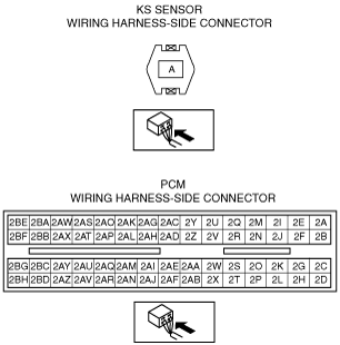
1. Disconnect the KS connector.
2. Measure the resistance between KS terminal A and body ground.
-
• If the monitor item condition/specification (reference) is not within the specification, even though there is no malfunction, perform the “Circuit Open/Short Inspection”.
-
KS resistance
-
532—588 kilohms [20 °C {68 °F}]
Circuit Open/Short Inspection (Without Throttle Valve Actuator)
1. Remove the PCM connector cover.
2. Disconnect the PCM connector. (See INTAKE-AIR SYSTEM REMOVAL/INSTALLATION[ZJ, ZY, Z6].)
3. Inspect the following wiring harness for open or short circuit (continuity check).
Open circuit
-
• If there is no continuity, there is an open circuit. Repair or replace the wiring harness.
-
― Knock sensor terminal A and PCM terminal 2BA
Short circuit
-
• If there is continuity, there is a short circuit. Repair or replace the wiring harness.
-
― Knock sensor terminal A and body ground
― Knock sensor terminal A and power supply
Circuit Open/Short Inspection (With Throttle Valve Actuator)
1. Remove the PCM connector cover.
2. Disconnect the PCM connector. (See INTAKE-AIR SYSTEM REMOVAL/INSTALLATION[ZJ, ZY, Z6].)
3. Inspect the following wiring harness for open or short circuit (continuity check).
Open circuit
-
• If there is no continuity, there is an open circuit. Repair or replace the wiring harness.
-
― Knock sensor terminal A and PCM terminal 2AN
Short circuit
-
• If there is continuity, there is a short circuit. Repair or replace the wiring harness.
-
― Knock sensor terminal A and body ground
― Knock sensor terminal A and power supply