 |
am3zzn00000570
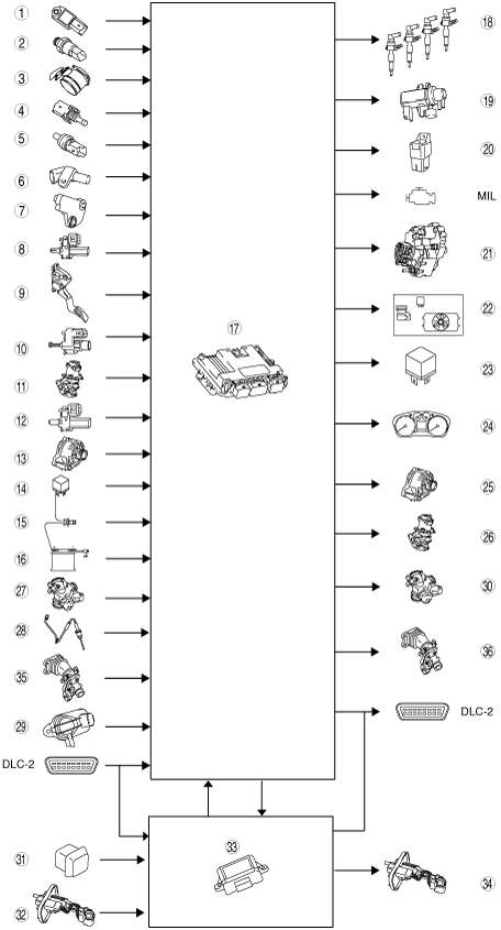
ENGINE CONTROL SYSTEM BLOCK DIAGRAM[MZ-CD 1.6 (Y6)]
id0140b2100500
am3zzn00000570
|
|
1
|
MAP sensor
|
|
2
|
Fuel pressure sensor
|
|
3
|
Combined IAT sensor and MAF sensor
|
|
4
|
Fuel temperature sensor
|
|
5
|
ECT sensor
|
|
6
|
CMP sensor
|
|
7
|
CKP sensor
|
|
8
|
Brake switch
|
|
9
|
APP sensor
|
|
10
|
BPP switch
|
|
11
|
EGR valve (EGR valve position sensor)
|
|
12
|
CPP switch
|
|
13
|
Generator (input signal)
|
|
14
|
Start relay
|
|
15
|
Engine switch
|
|
16
|
Battery
|
|
17
|
PCM (Built-in BARO sensor)
|
|
18
|
Fuel injector
|
|
19
|
VBC solenoid valve
|
|
20
|
Glow plug relay
|
|
21
|
Fuel pump with fuel metering valve
|
|
22
|
A/C relay
|
|
23
|
PCM control relay
|
|
24
|
Instrument cluster
|
|
25
|
Generator (output signal)
|
|
26
|
EGR valve (EGR valve servo motor)
|
|
27
|
Air bypass valve position sensor, intake throttle valve position sensor and IAT sensor No.2 (High power-Euro 4)
|
|
28
|
Catalyst exhaust gas temperature sensor (High power-Euro 4)
|
|
29
|
Diesel particulate filter differential pressure sensor (High power-Euro 4)
|
|
30
|
Air bypass valve actuator and intake throttle valve actuator (High power-Euro 4)
|
|
31
|
Fuel-filler switch (High power-Euro 4)
|
|
32
|
Fuel additive level sensor (High power-Euro 4)
|
|
33
|
Fuel additive control module (High power-Euro 4)
|
|
34
|
Fuel additive pump unit (High power-Euro 4)
|
|
35
|
Intake throttle valve position sensor and IAT sensor NO.2 (Standard power-Euro 4)
|
|
36
|
Intake throttle valve actuator (Standard power-Euro 4)
|