 |
am3zzn00001211
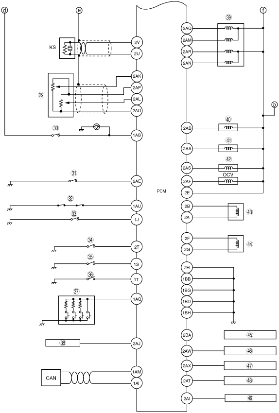
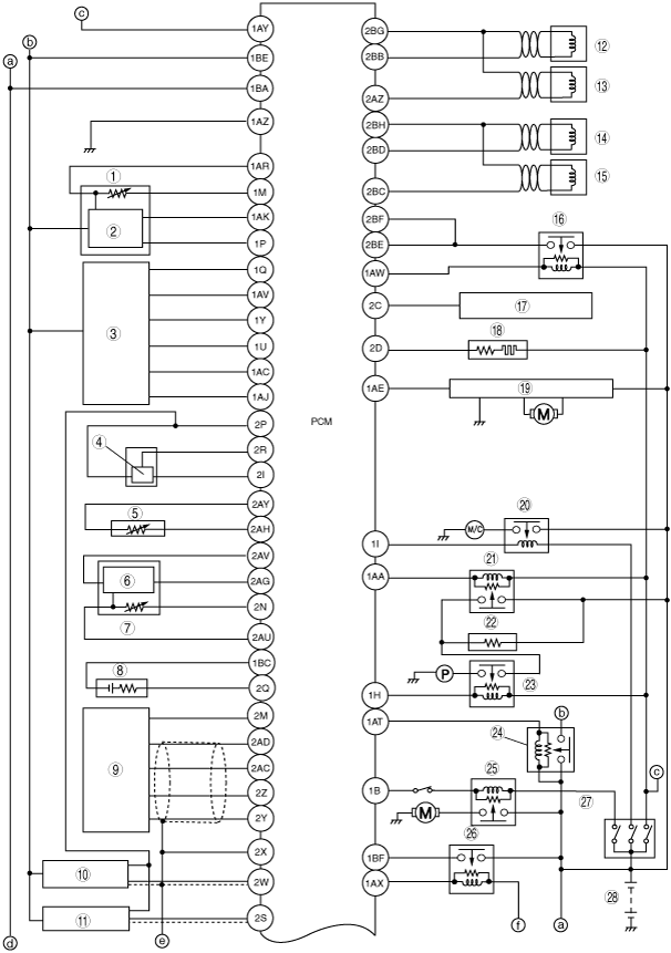
ENGINE CONTROL SYSTEM WIRING DIAGRAM [L3 Turbo]
id0140b6100400
am3zzn00001211
|
|
1
|
IAT sensor
|
|
2
|
MAF sensor
|
|
3
|
APP sensor
|
|
4
|
Fuel pressure sensor
|
|
5
|
ECT sensor
|
|
6
|
MAP sensor
|
|
7
|
Boost air temperature sensor
|
|
8
|
HO2S
|
|
9
|
A/F sensor
|
|
10
|
CKP sensor
|
|
11
|
CMP sensor
|
|
12
|
Fuel injector No.1
|
|
13
|
Fuel injector No.4
|
|
14
|
Fuel injector No.3
|
|
15
|
Fuel injector No.2
|
|
16
|
Fuel injector relay
|
|
17
|
A/F sensor heater
|
|
18
|
HO2S heater
|
|
19
|
Fan control module
|
|
20
|
A/C relay
|
|
21
|
Fuel pump speed control relay
|
|
22
|
Fuel pump resistor
|
|
23
|
Fuel pump relay
|
|
24
|
Main relay
|
|
25
|
Starter relay
|
|
26
|
Drive-by-wire-relay
|
|
27
|
Ignition switch
|
|
28
|
Battery
|
am3zzn00001479
|
|
29
|
TP sensor
|
|
30
|
Brake switch No.1
|
|
31
|
Variable swirl shutter valve switch
|
|
32
|
Refrigerant pressure switch (high, low)
|
|
33
|
Refrigerant pressure switch (middle)
|
|
34
|
PSP switch
|
|
35
|
Neutral switch
|
|
36
|
CPP switch
|
|
37
|
Cruise control switch
|
|
38
|
Generator
|
|
39
|
EGR valve
|
|
40
|
Purge solenoid valve
|
|
41
|
Wastegate control solenoid valve
|
|
42
|
Variable swirl solenoid valve
|
|
43
|
Throttle actuator
|
|
44
|
Spill valve control solenoid valve
|
|
45
|
Ignition coil No.1
|
|
46
|
Ignition coil No.2
|
|
47
|
Ignition coil No.3
|
|
48
|
Ignition coil No.4
|
|
49
|
Generator
|