FUEL INJECTION CONTROL OPERATION [L3 Turbo]
id0140b6101900
Operation
Injection timing
-
• A synchronized fuel injection at the set crank position is performed.
-
Synchronized fuel injection
-
• Fuel injection is performed with the appropriate injection timing and amount based on the below sensor input signals synchronized with the crankshaft rotation during the intake air process at each cylinder.
-
― CKP sensor
― MAF sensor
― ECT sensor
― IAT sensor
― BARO sensor
Injection Time
• The PCM calculates the fuel injection amount according to the engine operation conditions at fuel injection and energizes the fuel injectors.
Fuel injector energization time and operation conditions
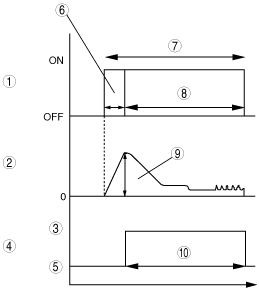
• The fuel injectors cause an operation delay with the start of energization from the PCM. The PCM calculates the fuel injection time by adding the non-injection time (ineffective injection time) to the actual injection time (effective injection time), and energizes the fuel injectors for this time.
|
1
|
Injection signal
|
|
2
|
Fuel injector current
|
|
3
|
Open
|
|
4
|
Fuel injector
|
|
5
|
Closed
|
|
6
|
Ineffective injection time
|
|
7
|
Fuel injection time
|
|
8
|
Effective injection time
|
|
9
|
Fuel injector opening valve electrical current
|
|
10
|
Fuel injector valve opening time
|
• The fuel injection time is based on the following formula:
Fuel injection time = effective injection time + ineffective injection time
Ineffective injection time
-
― The fuel injectors cause an operation delay due to a delay in the rise of operation current due to coil inductance at the start of energization, and by the mass of the needle valve and plunger, and spring resistance. This delay is the ineffective injection time.
― The non-injection time is affected by the change in fuel pressure. Accordingly, the PCM sets the non-injection time according to the fuel pressure.
Effective injection time
-
― The fuel injector opening valve time, which is the actual fuel injection time, is called the effective injection time.
Determination of effective Injection Time
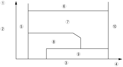
• The PCM divides the engine operation conditions into control zones according to engine speed and engine load, and determines the effective injection time at each control zone to perform optimum air/fuel ratio control in all engine driving ranges.
|
1
|
Large
|
|
2
|
Intake air amount
|
|
3
|
Engine speed
|
|
4
|
High
|
|
5
|
Start zone
|
|
6
|
Overboost fuel cut zone
|
|
7
|
High load volume increase feedback zone
|
|
8
|
Lambda 1 feedback zone
|
|
9
|
Deceleration fuel cut zone
|
|
10
|
Excessive speed fuel cut zone
|
Overboost fuel cut zone
-
Purpose
-
• Intake air system component protection
-
Control condition
-
• Manifold absolute pressure or charging efficiency is at the given value or more.
-
Determination of fuel injection time
-
• The fuel injection time is set to 0 (fuel cut).
Start zone
-
Purpose
-
• Improved startability
-
Control condition
-
• When engine speed is 500 rpm or less
-
Determination of fuel injection time
-
• Determination is based on the engine coolant temperature (ECT sensor) and engine speed (CKP sensor)
Lambda 1 feedback zone
-
Purpose
-
• Improved fuel economy
• Improved exhaust gas purification
-
Control condition
-
• Occurs during engine operation except for high load volume increases and engine start zones
-
Determination of fuel injection time
-
• During normal driving, the various correction amounts are added to the basic injection time to obtain the ratio that is close to the theoretical air/fuel ratio.
High load volume increase feedback zone
-
Purpose
-
• Improved driveability, exhaust system component protection (suppress gas temperature)
-
Control condition
-
• Either the charging efficiency or the accelerator opening angle is a given value or more.
-
Determination of fuel injection time
-
• Corrections are added to the basic injection amount and the high load coefficient is calculated according to the engine speed, mass intake airflow amount and the throttle valve opening angle.
Excessive speed fuel cut zone
-
Purpose
-
• Engine protection
-
Control condition
-
• When the engine speed is 6,800 rpm or more (WOT).
• When engine speed is 5,500 rpm or more and the engine coolant temprature is approx. -15°C {5°F} or less.
• All of the following conditions are met while the vehicle is stopped.
-
― Engine speed of 1,500 rpm or more continues for 5 min.
― Engine speed of 3,500 rpm or more continues for 2 min.
― Engine speed of 6,000 rpm or more continues for 10 s.
-
Note
-
• The PCM determines that the driver continues to unintentionally depress the accelerator pedal
-
Determination of fuel injection time
-
• The fuel injection time is set to 0 (fuel cut).
Deceleration fuel cut zone
-
Purpose
-
• Improved fuel economy
• Prevents overheating of the catalytic converter.
-
Control condition
-
• When the engine conditions are as follows10 s or more has elapsed after engine start).
-
― Accelerator pedal position is fully closed
― Engine speed is the set value or more (charging efficiency at given value or more, mass airflow sensor normal).
-
Determination of fuel injection time
-
• The fuel injection time is set to 0 (fuel cut)
Fuel injection time calculation method table
(A: Fuel injection time base, B: Correction for fuel injection time)
|
Contents
(Fuel injection time, calculation method, or determination method)
|
Control zone
|
|
|
|
High load volume increase
|
|
|
|
|
Injection time at start
|
Set value according to engine coolant temperature (low engine coolant temperature→long injection time)
|
A
|
|
|
|
|
|
|
Basic injection time
|
Basic injection time = charging efficiency x fuel flow coefficient
|
|
A
|
A
|
|
|
|
|
Fuel cut
|
Fuel injection time = 0
|
|
|
|
A
|
A
|
A
|
|
Ineffective injection time
|
Set time according to injector performance
|
A
|
A
|
A
|
|
|
|
|
Volume increase correction at engine start
|
Purpose: Ensures engine speed stability just after engine start
Correction condition
• Specified time according to the engine coolant temperature directly after engine start
Correction amount
• Low engine coolant temperature→large correction
• High intake air temperature→large correction
|
B
|
B
|
|
|
|
|
|
Lambda 1 feedback correction
|
Purpose: Controls air/fuel ratio to target air/fuel ratio
Correction condition
• When the engine coolant temperature is at the set value or more
Correction amount
• A/F sensor lambda value 1 or less→fuel volume decrease correction
• A/F sensor lambda value 1 or more→fuel volume increase correction
|
|
B
|
|
|
|
|
|
HO2S feedback correction
|
Purpose: Corrects feedback amount according to deterioration of A/F sensor and catalytic converter
Correction condition
• Engine coolant temperature is at set value or more
• Engine speed is 500—3,600 rpm
• Charging efficiency is 10—80%
Correction amount
• According to HO2S electromotive force→correction
|
|
B
|
|
|
|
|
|
High load value increase feedback correction
|
Purpose: Improved engine output, decrease of exhaust gas temperature
Correction condition
• Based on the engine speed when the accelerator opening angle is the fixed value or more, otherwise, based on the engine speed and charging efficiency.
Correction amount
• High engine speed, high charging efficiency→large correction
|
|
|
B
|
|
|
|
|
Warm-up volume increase correction
|
Purpose: Ensures combustion stability when the engine coolant temperature is low
Correction condition
• While at the set engine coolant temperature
Correction amount
• High charging efficiency, low engine coolant temperature→large correction
|
|
B
|
B
|
|
|
|
|
Volume increase correction during acceleration
|
Purpose: Corrects fuel injection delay during acceleration, to ensure drive stability
Correction condition
• When the acceleration amount (change in the amount of charging efficiency) is at the set value or more.
Correction amount
• Low engine coolant temperature→large correction
• Large acceleration amount→large correction
|
|
B
|
B
|
|
|
|
|
Learning correction
|
Purpose: Corrects deviation in air/fuel ratio from deterioration over time of mechanical devices
Correction condition
• Under any condition except purge control
Correction amount
• Learning value based on average of feedback correction value
|
|
B
|
B
|
|
|
|
Fuel Cut
• Includes fuel cut under the following condition, except for fuel cut at excessive engine speed, deceleration, sensor malfunction, overspeed, and dechoke according to engine operation.
Overboost fuel cut
-
• Purpose
-
• Intake air system component protection
• Control conditions
-
• Manifold absolute pressure or charging efficiency is at the given value or more
Boost Circuit
• The battery positive voltage input via the injector driver relay is boosted up to 100 V.
Output Circuit
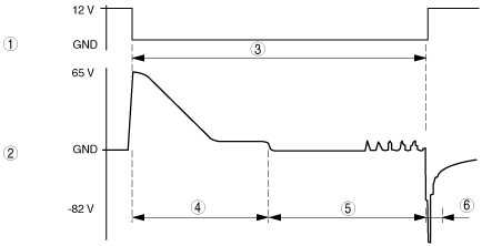
• To improve fuel injection response, the plunger pulling force is strengthened by providing high current (over excitation current) when the fuel injector is open.
• To reduce fuel injector heat generation, the opening of the fuel injector is kept opened using low current after it opens.
|
Fuel injector status
|
Injector driver module operation
|
|
Opening starts
|
1. Provides 65 V, boosted by the boost circuit, to the opening transistor (65 V output).
2. When the voltage is provided to the fuel injector and turns on the GND transistor, the fuel injector opens.
3. After the fuel injector is opened, the opening transistor is turned off.
|
|
Opening held
|
• Controls the on/off of the holding transistor (12 V output) so that the hold current of the fuel injector is constant.
|
|
Closing
|
• Turns off the holding and GND transistors at the same time the fuel injection signal from the PCM is stopped, and cuts the current.
|
Fuel Injection Verification Circuit
• The fuel injection verification circuit detects the breaking current (surge voltage) generated during the opening. The PCM detects a malfunction in the fuel injector circuit based on this signal.
|
1
|
Fuel injector signal input
|
|
2
|
Fuel injector signal output
|
|
3
|
Fuel injector operation period
|
|
4
|
Excess exciting current
|
|
5
|
Hold current
|
|
6
|
Close current
|
• The fuel injector signal output shown in the figure indicates the waveform when both ends of the fuel injector are measured.