am3zzn00001235
|
|
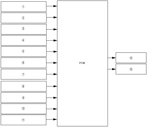
1
|
ECT sensor
|
|
2
|
MAF sensor
|
|
3
|
APP sensor No.1, No.2
|
|
4
|
CKP sensor
|
|
5
|
BARO sensor
|
|
6
|
Refrigerant pressure switch (middle)
|
|
7
|
Refrigerant pressure switch (high and low)
|
|
8
|
Ignition switch
|
|
9
|
Vehicle speed signal
|
|
10
|
Instrument cluster (A/C on request signal)
|
|
11
|
IAT sensor
|
|
12
|
Fan control module
|
|
13
|
Cooling fan relay
|