 |
acxuuw00000125
PCM INSPECTION [L3 Turbo]
id0140b6802500
Without Using the M-MDS
PCM terminal voltage table (Reference)
acxuuw00000125
|
|
Terminal |
Signal |
Connected to |
Test condition |
Voltage (V) |
Inspection item |
|
|---|---|---|---|---|---|---|
|
1A
|
—
|
—
|
—
|
—
|
—
|
|
|
1B
|
Starter relay control
|
Starter relay
|
Ignition switch off after 10 s
|
Below 1.0
|
• Starter relay
• Related wiring harness
|
|
|
Ignition switch to the ON position
|
Below 1.0
|
|||||
|
1C
|
—
|
—
|
—
|
—
|
—
|
|
|
1D
|
Clutch operation
|
CPP switch
|
Clutch pedal depressed
|
Below 1.0
|
• CPP switch
• Related wiring harness
|
|
|
Clutch pedal released
|
B+
|
|||||
|
1E
|
—
|
—
|
—
|
—
|
—
|
|
|
1F
|
—
|
—
|
—
|
—
|
—
|
|
|
1G
|
—
|
—
|
—
|
—
|
—
|
|
|
1H
|
Fuel pump control
|
Fuel pump relay
|
Ignition switch to the ON position after 10 s
|
B+
|
• Fuel pump relay
• Related wiring harness
|
|
|
Cranking
|
B+
|
|||||
|
Idle
|
Below 1.0
|
|||||
|
1I
|
A/C
|
A/C relay
|
Idle
|
A/C operating
|
Below 1.0
|
• A/C relay
• Related wiring harness
|
|
A/C not operating
|
B+
|
|||||
|
1J
|
Refrigerant pressure switch (middle)
|
Refrigerant pressure switch (middle)
|
A/C ON
|
Refrigerant pressure is more than the specification. (Refrigerant pressure switch (middle) is on.)
|
Below 1.0
|
• Refrigerant pressure switch
• Related wiring harness
|
|
Refrigerant pressure is less than the specification. (Refrigerant pressure switch (middle) is off.)
|
B+
|
|||||
|
1K
|
—
|
—
|
—
|
—
|
—
|
|
|
1L
|
—
|
—
|
—
|
—
|
—
|
|
|
1M
|
IAT
|
MAF/IAT sensor
|
Ignition switch to the ON position
|
IAT 20 °C
{68 °F}
|
Approx. 2.38
|
• MAF/IAT sensor
• Related wiring harness
|
|
IAT 40 °C
{104 °F}
|
Approx. 1.49
|
|||||
|
1N
|
—
|
—
|
—
|
—
|
—
|
|
|
1O
|
—
|
—
|
—
|
—
|
—
|
|
|
1P
|
MAF sensor ground
|
MAF/IAT sensor
|
Under any condition
|
Below 1.0
|
• Related wiring harness
|
|
|
1Q
|
—
|
—
|
—
|
—
|
—
|
|
|
1R
|
—
|
—
|
—
|
—
|
—
|
|
|
1S
|
Neutral position
|
Neutral switch
|
Shift lever is at neutral position
|
Below 1.0
|
• Neutral switch
• Related wiring harness
|
|
|
Shift lever is not at neutral position
|
B+
|
|||||
|
1T
|
—
|
—
|
—
|
—
|
—
|
|
|
1U
|
APP sensor ground
|
APP sensor
|
Under any condition
|
Below 1.0
|
• APP sensor
• Related wiring harness
|
|
|
1V
|
—
|
—
|
—
|
—
|
—
|
|
|
1W
|
—
|
—
|
—
|
—
|
—
|
|
|
1X
|
—
|
—
|
—
|
—
|
—
|
|
|
1Y
|
APP (No.1)
|
APP sensor
|
Ignition switch to the ON position
|
Accelerator pedal depressed
|
Approx. 3.0
|
• APP sensor
• Related wiring harness
|
|
Accelerator pedal released
|
Approx. 0.4
|
|||||
|
1Z
|
—
|
—
|
—
|
—
|
—
|
|
|
1AA
|
Fuel pump speed control
|
Fuel pump speed control relay
|
Ignition switch to the ON position after 10 s
|
B+
|
• Fuel pump speed control relay
• Related wiring harness
|
|
|
Cranking
|
Below 1.0
|
|||||
|
Idle
|
Below 1.0
|
|||||
|
1AB
|
Brake
|
Brake switch
|
Brake pedal depressed
|
B+
|
• Brake switch
• Related wiring harness
|
|
|
Brake pedal released
|
Below 1.0
|
|||||
|
1AC
|
APP (No.2)
|
APP sensor (No.2)
|
• Inspect using the wave profile.
|
• APP sensor
• Related wiring harness
|
||
|
1AD
|
—
|
—
|
—
|
—
|
—
|
|
|
1AE
|
Fan control module
|
Fan control module
|
• Inspect using the wave profile.
|
• Fan control module
• Related wiring harness
|
||
|
1AF
|
—
|
—
|
—
|
—
|
—
|
|
|
1AG
|
—
|
—
|
—
|
—
|
—
|
|
|
1AH
|
—
|
—
|
—
|
—
|
—
|
|
|
1AI
|
CAN (L)
|
CAN related module
|
Because this terminal is for CAN, no valid determination of terminal voltage is possible
|
• Related wiring harness
|
||
|
1AJ
|
Constant voltage
|
APP sensor
|
Ignition switch to the ON position
|
Approx. 5.0
|
• Related wiring harness
|
|
|
1AK
|
MAF
|
MAF/IAT sensor
|
Ignition switch to the ON position
|
Approx. 0.7
|
• MAF/IAT sensor
• Related wiring harness
|
|
|
Idle
|
Approx. 1.3
|
|||||
|
1AL
|
—
|
—
|
—
|
—
|
—
|
|
|
1AM
|
CAN (H)
|
CAN related module
|
Because this terminal is for CAN, no valid determination of terminal voltage is possible
|
• Related wiring harness
|
||
|
1AN
|
—
|
—
|
—
|
—
|
—
|
|
|
1AO
|
—
|
—
|
—
|
—
|
—
|
|
|
1AP
|
—
|
—
|
—
|
—
|
—
|
|
|
1AQ
|
Cruise control switch
|
Cruise control switch
|
Ignition switch to the ON position
|
ON/OFF switch pressed in
|
Approx. 0
|
• Cruise control switch
• Related wiring harness
|
|
CANCEL switch pressed in
|
Approx. 1.1
|
|||||
|
SET/COAST switch pressed in
|
Approx. 3.1
|
|||||
|
RES/ACCEL switch pressed in
|
Approx. 4.2
|
|||||
|
Except above
|
Approx. 5.0
|
|||||
|
1AR
|
IAT sensor ground
|
MAF/IAT sensor
|
Under any condition
|
Below 1.0
|
• Related wiring harness
|
|
|
1AS
|
—
|
—
|
—
|
—
|
—
|
|
|
1AT
|
Main relay control
|
Main relay
|
Ignition switch off after 10 s
|
B+
|
• Main relay
• Related wiring harness
|
|
|
Ignition switch to the ON position
|
Below 1.0
|
|||||
|
1AU
|
A/C on signal
|
Refrigerant pressure switch (high, low)
|
Idle
|
A/C switch and fan switch on
|
B+
|
• Refrigerant pressure switch (high, low)
• Related wiring harness
|
|
1AV
|
APP sensor ground
|
APP sensor
|
Under any condition
|
Below 1.0
|
• Related wiring harness
|
|
|
1AW
|
Fuel injector control
|
Fuel Injector relay
|
Under any condition
|
Below 1.0
|
• Related wiring harness
|
|
|
1AX
|
Drive-by-wire relay control
|
Drive-by-wire relay
|
Ignition switch off after 10 s
|
Below 1.0
|
• Related wiring harness
|
|
|
Ignition switch to the ON position
|
Below 1.0
|
|||||
|
1AY
|
Ignition switch
|
Ignition switch
|
Ignition switch off
|
Below 1.0
|
• Related wiring harness
|
|
|
Ignition switch to the ON position
|
B+
|
|||||
|
1AZ
|
Ground
|
Ground
|
Under any condition
|
Below 1.0
|
• Related wiring harness
|
|
|
1BA
|
Back-up power supply
|
Battery (positive terminal)
|
Under any condition
|
B+
|
• Battery
• Related wiring harness
|
|
|
1BB
|
Ground
|
Ground
|
Under any condition
|
Below 1.0
|
• Related wiring harness
|
|
|
1BC
|
Sensor ground
|
HO2S
|
Under any condition
|
Below 1.0
|
• HO2S
• Related wiring harness
|
|
|
1BD
|
Ground
|
Ground
|
Under any condition
|
Below 1.0
|
• Related wiring harness
|
|
|
1BE
|
B+
|
Main relay
|
Ignition switch off after 10 s
|
Below 1.0
|
• Battery
• Related wiring harness
|
|
|
Ignition switch to the ON position
|
B+
|
|||||
|
1BF
|
Throttle actuator power supply
|
Drive-by-wire relay
|
Ignition switch off after 10 s
|
Below 1.0
|
• Related wiring harness
|
|
|
Ignition switch to the ON position
|
B+
|
|||||
|
1BG
|
Ground
|
Ground
|
Under any condition
|
Below 1.0
|
• Related wiring harness
|
|
|
1BH
|
Ground
|
Ground
|
Under any condition
|
Below 1.0
|
• Related wiring harness
|
|
|
2A
|
Throttle actuator control (+)
|
Throttle body
|
Ignition switch off
|
Approx. 1.5
|
• Throttle actuator
• Related wiring harness
|
|
|
Ignition switch to the ON position
|
B+
|
|||||
|
2B
|
Throttle actuator control (–)
|
Throttle body
|
Ignition switch off
|
Approx. 1.5
|
• Throttle actuator
• Related wiring harness
|
|
|
Ignition switch to the ON position
|
B+
|
|||||
|
2C
|
A/F sensor heater control
|
A/F sensor heater
|
• Inspect using the wave profile.
|
• A/F sensor
• Related wiring harness
|
||
|
2D
|
HO2S heater control
|
HO2S heater
|
• Engine speed above 5,000 rpm (Heater control not operating)
|
B+
|
• HO2S heater
• Related wiring harness
|
|
|
2E
|
Power supply
|
Main relay, Variable swirl solenoid valve, CMP sensor
|
Ignition switch off after 10 s
|
Below 1.0
|
• Main relay
• Related wiring harness
|
|
|
Ignition switch to the ON position
|
B+
|
|||||
|
2F
|
High pressure fuel pump control (+)
|
High pressure fuel pump
|
Ignition switch off
|
Below 1.0
|
• High pressure fuel pump
• Related wiring harness Related wiring harness
|
|
|
Ignition switch to the ON position
|
Approx. 9.7
|
|||||
|
Idle
|
Approx. 9.4
|
|||||
|
2G
|
High pressure fuel pump control (–)
|
High pressure fuel pump
|
Ignition switch off
|
Below 1.0
|
• High pressure fuel pump
• Related wiring harness Related wiring harness
|
|
|
Ignition switch to the ON position
|
Approx. 9.6
|
|||||
|
Idle
|
Approx. 8.6
|
|||||
|
2H
|
Ground
|
Body ground
|
Under any condition
|
Below 1.0
|
• Related wiring harness
|
|
|
2I
|
Constant voltage (Vref)
|
Fuel pressure sensor
|
Ignition switch to the ON position
|
Approx. 5.0
|
• Related wiring harness
|
|
|
2J
|
—
|
—
|
—
|
—
|
—
|
|
|
2K
|
—
|
—
|
—
|
—
|
—
|
|
|
2L
|
—
|
—
|
—
|
—
|
—
|
|
|
2M
|
Sensor ground
|
A/F sensor
|
Under any condition
|
Below 1.0
|
• Related wiring harness
|
|
|
2N
|
Boost air temperature
|
MAP/Boost air temperature sensor
|
Ignition switch to the ON position
|
IAT 20 °C
{68 °F}
|
2.4—2.6
|
• Boost air temperature sensor
• Related wiring harness
|
|
IAT 30 °C
{86 °F}
|
1.7—1.9
|
|||||
|
2O
|
—
|
—
|
—
|
—
|
—
|
|
|
2P
|
Sensor ground
|
Fuel pressure sensor
|
Under any condition
|
Below 1.0
|
• Fuel pressure sensor
• Related wiring harness
|
|
|
2Q
|
HO2S
|
HO2S
|
Idle
|
0—1
|
• HO2S
• Related wiring harness
|
|
|
2R
|
Fuel pressure sensor
|
Fuel pressure sensor
|
Idle (after warm up)
|
Approx. 1.35
|
• Fuel pressure sensor
• Related wiring harness
|
|
|
2S
|
CMP
|
CMP sensor
|
• Inspect using the wave profile.
|
• CMP sensor
• Related wiring harness
|
||
|
2T
|
PSP
|
PSP switch
|
Idle
|
Steering wheel at straight ahead position
|
B+
|
• PSP switch
• Power steering system
• Related wiring harness
|
|
While turning steering wheel
|
Below 1.0
|
|||||
|
2U
|
Knocking (+)
|
KS
|
Ignition switch to the ON position (Use digital type voltmeter, because measurement voltage will be detected less than true voltage when using analog type voltmeter)
|
Approx. 4.3
|
• KS
• Related wiring harness
|
|
|
2V
|
Knocking (–)
|
KS
|
Ignition switch to the ON position (Use digital type voltmeter, because measurement voltage will be detected less than true voltage when using analog type voltmeter)
|
Below 1.0
|
• KS
• Related wiring harness
|
|
|
2W
|
CKP
|
CKP sensor
|
• Inspect using the wave profile.
|
• CKP sensor
• Related wiring harness
|
||
|
2X
|
Internal ground
|
KS, CMP sensor, CKP sensor, A/F sensor, TP sensor
|
Under any condition
|
Below 1.0
|
• Related wiring harness
|
|
|
2Y
|
A/F sensor calibration resistor
|
A/F sensor
|
Ignition switch off after 10s
|
Below 1.0
|
• A/F sensor
• Related wiring harness
|
|
|
Ignition switch to the ON position
|
Approx. 3.9
|
|||||
|
2Z
|
A/F sensor power supply
|
A/F sensor
|
Idle (after warm up)
|
Approx. 6.2
|
• A/F sensor
• Related wiring harness
|
|
|
2AA
|
Wastegate control solenoid valve
|
Wastegate control solenoid valve
|
• Inspect using the wave profile.
|
• Wastegate control solenoid valve
• Related wiring harness
|
||
|
2AB
|
Purge solenoid valve
|
Purge solenoid valve
|
• Inspect using the wave profile.
|
• Purge solenoid valve
• Related wiring harness
|
||
|
2AC
|
A/F sensor
|
A/F sensor
|
Idle (after warm up)
|
Approx. 3.7
|
• A/F sensor
• Related wiring harness
|
|
|
2AD
|
A/F sensor
|
A/F sensor
|
Idle (after warm up)
|
Approx. 3.7
|
• A/F sensor
• Related wiring harness
|
|
|
After racing
|
2.1—4.8
|
|||||
|
2AE
|
Variable swirl shutter valve monitor
|
Variable swirl shutter valve switch
|
variable swirl shutter valve close
|
Below 1.0
|
• Variable swirl shutter valve switch
• Related wiring harness
|
|
|
variable swirl shutter valve open
|
B+
|
|||||
|
2AF
|
OCV control
|
OCV
|
• Inspect using the wave profile.
|
• OCV valve
• Related wiring harness
|
||
|
2AG
|
Manifold absolute pressure
|
MAP sensor
|
Ignition switch to the ON position)
|
Approx. 1.9
|
• MAP sensor
• Related wiring harness
|
|
|
Idle (after warm up)
|
Below 1.0
|
|||||
|
2AH
|
ECT
|
ECT sensor
|
Ignition switch to the ON position
|
ECT 20 °C
{68 °F}
|
3.04—3.14
|
• ECT sensor
• Related wiring harness
|
|
ECT 60 °C
{140 °F}
|
1.29—1.39
|
|||||
|
2AI
|
Generator field coil control
|
Generator
(terminal D)
|
• Inspect using the wave profile.
|
• Generator
• Related wiring harness
|
||
|
2AJ
|
Generator output voltage
|
Generator
(terminal P)
|
• Inspect using the wave profile.
|
• Generator
• Related wiring harness
|
||
|
2AK
|
TP (No. 1)
|
TP sensor (No. 1)
|
Ignition switch to the ON position
|
APP is released
|
Approx. 0.95
|
• TP sensor
• Related wiring harness
|
|
Idle (after warm up)
|
Gradually depress the accelerator pedal while verifying that the voltage changes.
|
|||||
|
2AL
|
TP (No. 2)
|
TP sensor (No. 2)
|
Ignition switch to the ON position
|
APP is released
|
Approx. 4.03
|
• TP sensor
• Related wiring harness
|
|
Idle (after warm up)
|
Gradually depress the accelerator pedal while verifying that the voltage changes.
|
|||||
|
2AM
|
EGR valve #3 coil control
|
EGR valve
(terminal A)
|
Ignition switch to the ON position
|
B+
|
• EGR valve
• Related wiring harness
|
|
|
Ignition switch off
|
Below 1.0
|
|||||
|
2AN
|
EGR valve #6 coil control
|
EGR valve
(terminal F)
|
Ignition switch to the ON position
|
B+
|
• EGR valve
• Related wiring harness
|
|
|
Idle
|
B+
|
|||||
|
2AO
|
Constant voltage (Vref)
|
TP sensor
|
Ignition switch to the ON position
|
Approx. 5.0
|
• TP sensor
• Related wiring harness
|
|
|
2AP
|
TP sensor ground
|
TP sensor
|
Under any condition
|
Below 1.0
|
• TP sensor
• Related wiring harness
|
|
|
2AQ
|
EGR valve #1 coil control
|
EGR valve
(terminal E)
|
Ignition switch to the ON position
|
Below 1.0
|
• EGR valve
• Related wiring harness
|
|
|
Idle
|
Below 1.0
|
|||||
|
2AR
|
EGR valve #4 coil control
|
EGR valve
(terminal B)
|
Ignition switch to the ON position
|
B+
|
• EGR valve
• Related wiring harness
|
|
|
Ignition switch off
|
Below 1.0
|
|||||
|
2AS
|
Variable swirl control
|
Variable swirl solenoid valve
|
ECT 62 °C {144 °F} or more and engine speed 3,250 rpm or more
|
B+
|
• Variable swirl solenoid valve
• Related wiring harness
|
|
|
ECT less than 62 °C {144 °F} and engine speed less than3,250 rpm
|
Below 1.0
|
|||||
|
2AT
|
IGT4
|
Ignition coil (No.4 cylinders)
|
• Inspect using the wave profile.
|
• Ignition coil No.4
• Related wiring harness
|
||
|
2AU
|
Constant voltage (Vref)
|
MAP sensor
|
Ignition switch to the ON position
|
Approx. 5.0
|
• Related wiring harness
|
|
|
2AV
|
Sensor ground
|
MAP sensor
|
Under any condition
|
Below 1.0
|
• Related wiring harness
|
|
|
2AW
|
IGT2
|
Ignition coil (No.2 cylinders)
|
• Inspect using the wave profile.
|
• Ignition coil No.2
• Related wiring harness
|
||
|
2AX
|
IGT3
|
Ignition coil (No.3 cylinders)
|
• Inspect using the wave profile.
|
• Ignition coil No.3
• Related wiring harness
|
||
|
2AY
|
Sensor ground
|
ECT sensor
|
Under any condition
|
Below 1.0
|
• ECT sensor
• Related wiring harness
|
|
|
2AZ
|
Fuel injection
(–)(#4)
|
Fuel injector (No.4)
|
• Inspect using the wave profile.
|
• Fuel injector No.4
• Related wiring harness
|
||
|
2BA
|
IGT1
|
Ignition coil (No.1 cylinders)
|
• Inspect using the wave profile.
|
• Ignition coil No.1
• Related wiring harness
|
||
|
2BB
|
Fuel injection
(–)(#1)
|
Fuel injector (No.1)
|
• Inspect using the wave profile.
|
• Fuel injector No.1
• Related wiring harness
|
||
|
2BC
|
Fuel injection
(–)(#2)
|
Fuel injector (No.2)
|
• Inspect using the wave profile.
|
• Fuel injector No.2
• Related wiring harness
|
||
|
2BD
|
Fuel injection
(–)(#3)
|
Fuel injector (No.3)
|
• Inspect using the wave profile.
|
• Fuel injector No.3
• Related wiring harness
|
||
|
2BE
|
Fuel injector power supply 1
|
Fuel Injector relay
|
Ignition switch off
|
Below 1.0
|
• Fuel Injector relay
• Related wiring harness
|
|
|
Ignition switch to the ON position
|
B+
|
|||||
|
2BF
|
Fuel injector power supply 2
|
Fuel Injector relay
|
Ignition switch off
|
Below 1.0
|
• Fuel Injector relay
• Related wiring harness
|
|
|
Ignition switch to the ON position
|
B+
|
|||||
|
2BG
|
Fuel injection
(+)(#1, #4)
|
Fuel injector (No.1,No.4)
|
• Inspect using the wave profile.
|
• Fuel injector No.1, No.4
• Related wiring harness
|
||
|
2BH
|
Fuel injection
(+)(#2, #3)
|
Fuel injector
(No.2, No.3)
|
• Inspect using the wave profile.
|
• Fuel injector No.2, No.3
• Related wiring harness
|
||
Inspection Using An Oscilloscope (Reference)
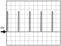
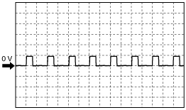
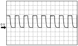
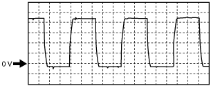
APP sensor signal
Accelerator pedal is released
aaxjjw00002881
|
Accelerator pedal is depressed
aaxjjw00002882
|
Fan control module signal
acxuuw00000274
|
A/F Sensor heater control signal
acxuuw00000275
|
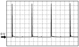
CMP sensor signal
acxuuw00000127
|
CKP sensor signal
acxuuw00000128
|
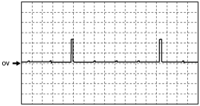
Wastegate control solenoid valve signal
acxuuw00002325
|
Purge control signal
ampjjw00001527
|
OCV signal
acxuuw00000129
|
Generator field coil control signal
ampjjw00001528
|
Generator output voltage signal
ampjjw00001529
|
IGT1, IGT2, IGT3, IGT4 control signals
ampjjw00000781
|
Fuel injection control (–)
acxuuw00002326
|
Fuel injection control (+)
acxuuw00000277
|
Using the M-MDS
1. Connect the M-MDS to the DLC-2.
am3zzw00000466
|
2. Turn the ignition switch to the ON position.
3. Measure the PID value.
PID/DATA monitor table (reference)
|
Monitor item (Definition) |
Unit/Condition |
Condition/Specification (Reference) |
Inspection item |
PCM terminal |
|
|---|---|---|---|---|---|
|
AC_REQ (Refrigerant pressure switch (high, low))
|
On/Off
|
Refrigerant pressure is more than the specification or less than the specification. (Refrigerant pressure switch (high, low) is off.): Off
Except above: On
|
• Refrigerant pressure switch (high, low)
|
1AU
|
|
|
ACCS (A/C relay)
|
On/Off
|
A/C relay is ON: On
A/C relay is OFF: Off
|
• The following PIDs:
• A/C relay
|
1I
|
|
|
AFR (Air fuel ratio)
|
—
|
Target air fuel ratio is displayed
|
• A/F sensor
|
2Z
2AC
2AD
|
|
|
AFR_ACT (Actual air fuel ratio)
|
—
|
Actual air fuel ratio is displayed
|
• A/F sensor
|
2Z
2AC
2AD
|
|
|
ALTF (Generator field coil control duty value)
|
%
|
Ignition switch to the ON position: 0%
Idle: 0—100%
Just after A/C switch ON and fan switch ON at idle: Duty value rises
|
• The following PIDs:
• Generator
|
2AI
|
|
|
ALTT V (Generator output voltage)
|
V
|
Idle (no E/L): Approx. 14 V (This is an internal calculation value and differs from the terminal voltage.)
|
• Generator
|
2AJ
|
|
|
APP (Accelerator pedal position)
|
%
|
Accelerator pedal is released: 0%
Accelerator pedal is depressed: 100%
|
• The following PIDs:
• APP sensor
|
1Y
1AC
|
|
|
APP1 (APP sensor N0.1)
|
V
|
• Accelerator pedal released: Approx. 0.4 V
• Accelerator pedal depressed: Approx. 3.0 V
|
• APP sensor
|
1Y
|
|
|
%
|
• Accelerator pedal released: Approx. 15 %
• Accelerator pedal depressed: Approx. 60 %
|
||||
|
APP2 (APP sensor N0.2)
|
V
|
• Accelerator pedal released: Approx. 0.4 V
• Accelerator pedal depressed: Approx. 3.0 V
|
• APP sensor
|
1AC
|
|
|
%
|
• Accelerator pedal released: Approx. 8 %
• Accelerator pedal depressed: Approx. 60 %
|
||||
|
ARPMDES (Target engine speed)
|
RPM
|
Shift position: P or N
― No load: 700 rpm
― E/L operating: 700 rpm
― P/S operating: 700 rpm
― A/C ON: 700 rpm
|
• The following PIDs:
• CKP sensor
|
—
|
|
|
BARO (Barometric pressure)
|
Pa
|
Indicate the atmospheric pressure
|
• BARO sensor
|
—
|
|
|
V
|
Ignition switch is ON at sea level: Approx. 4.0 V
|
||||
|
BAT
|
°C
|
Boost air temperature is displayed
|
• MAP/boost air temperature sensor
|
2N
|
|
|
BAT_V
|
V
|
Boost air temperature 20 °C {68 °F}: 2.4—2.6 V
|
• MAP/boost air temperature sensor
|
2N
|
|
|
Boost air temperature 30 °C {86 °F}: 1.7—1.9 V
|
|||||
|
BOO
(Brake switch)
|
On/Off
|
Brake pedal depressed: On
Brake pedal released: Off
|
• Brake switch
|
1AB
|
|
|
BPA
(Brake pressure applied switch)
|
On/Off
|
Brake pedal depressed: On
Brake pedal released: Off
|
• Brake switch
|
1AB
|
|
|
CATT11_DSD
(Estimated catalytic converter temperature)
|
°C
|
°F
|
Indicate the estimated catalytic converter temperature
|
• Perform applicable DTC troubleshooting.
|
—
|
|
CHRGLP (Generator warning light)
|
On/Off
|
Ignition switch to the ON position: On
Idle: Off
|
• Perform applicable DTC troubleshooting.
|
—
|
|
|
COLP (Refrigerant pressure switch (middle))
|
ON/OFF
|
Refrigerant pressure is more than the specification. (Refrigerant pressure switch (middle) is on.): On
Refrigerant pressure is less than the specification. (Refrigerant pressure switch (middle) is off.): Off
|
• Refrigerant pressure switch (middle)
|
1J
|
|
|
CPP
(Clutch pedal position)
|
On/Off
|
• Clutch pedal depressed: On
• Clutch pedal released: Off
|
CPP switch
|
1D
|
|
|
CPP/PNP
(Shift lever position)
|
Drive/Neutral
|
• Neutral position: Neutral
• Others: Drive
|
Neutral switch
|
1X
|
|
|
DTCCNT (Number of DTC detected)
|
—
|
Indicates number of DTC
|
• Perform applicable DTC troubleshooting.
|
—
|
|
|
ECT (Engine coolant temperature)
|
°C
|
°F
|
Indicate the ECT
|
• ECT sensor
|
2AH
|
|
V
|
ECT 20 °C {68 °F}: 3.04—3.14 V
ECT 60 °C {140 °F}: 1.29—1.39 V
|
||||
|
EQ_RAT11
(Equivalence ratio (lambda))
|
—
|
Idling after warm-up: Approx. 1
|
• Perform applicable DTC troubleshooting.
|
—
|
|
|
EQ_RAT11_DSD
(A/F sensor)
|
—
|
Idling after warm-up: Approx. 1
|
• Perform applicable DTC troubleshooting.
|
—
|
|
|
ETC_ACT (Electronic throttle control actual)
|
°
|
Indicate the desired TP by angle
|
• Perform applicable DTC troubleshooting.
|
2A
2B
|
|
|
ETC_DSD (Electronic throttle control desired)
|
%
|
Indicate the desired TP by percent
|
• The following PIDs:
• TP sensor
|
2A
2B
|
|
|
°
|
Indicate the desired TP by angle
|
||||
|
EVAPCP (Purge solenoid valve duty value)
|
%
|
Ignition switch to the ON position: 0%
Idle: 0%
|
• The following PIDs:
• Purge solenoid valve
|
2AB
|
|
|
FAN_DUTY
|
%
|
ECT less than 98 °C {208 °F}: 0%
ECT 100 °C {212 °F}: 30%
ECT 106 °C {223 °F}: 70%
ECT 110 °C {230 °F}: 100%
|
• Fan control module
|
1AE
|
|
|
FIA (Fuel injection amount)
|
—
|
Indicate the fuel injection amount.
|
• Fuel injector
• Fuel Injector relay
|
—
|
|
|
FP (Fuel pump relay)
|
On/Off
|
Idle: On
Cranking: On
|
• The following PIDs:
• Fuel pump relay
|
1H
|
|
|
FP_Hi_PRES
|
On/Off
|
Spill valve control solenoid valve work: On
Spill valve control solenoid valve don’t work: Off
|
• High pressure fuel pump
|
2F
2G
|
|
|
FUEL_PRES
|
Pa
|
Idle (after warm up): Approx. 3 MPa
Load 60 % or more: Approx. 11.5 MPa
|
• Fuel pressure sensor
|
2R
|
|
|
FUEL_PRES_V
|
V
|
Idle (after warm up): Approx. 1.35 V
|
• Fuel pressure sensor
|
2R
|
|
|
FUELPW (Fuel injector duration)
|
sec
|
Idle: Approx. 450—650 µs
|
• The following PIDs:
|
2AZ
2BB
2BC
2BD
|
|
|
FUELSYS
(Fuel system status)
|
OL/CL/
OL-Drive/
OL-Fault/
CL-Fault
|
Ignition switch to the ON position: OL_Drive
Idle (after warm up): CL
|
• The following PIDs:
• Fuel injector
|
—
|
|
|
GENVDSD
(Generator voltage desired)
|
V
|
Idle: Approx. 13.83 V*1(E/L not operating)
|
• Perform applicable DTC troubleshooting.
|
—
|
|
|
HTR11
(A/F sensor heater)
|
On/Off
|
Idle (after warm up): OnÛOff
|
• The following PIDs:
|
2C
|
|
|
HTR12
(HO2S heater)
|
On/Off
|
Idle: On
Engine speed is above 4,000 rpm: Off
|
• The following PIDs:
|
2D
|
|
|
IAT
(Intake air temperature)
|
°C
|
°F
|
Indicate the IAT
|
• MAF/IAT sensor
|
1M
|
|
V
|
IAT 20 °C {68 °F}: 2.4—2.6V
IAT 30 °C {86 °F}: 1.7—1.9V
|
||||
|
IMRC (Variable swirl solenoid valve)
|
On/Off
|
Engine speed is below Approx. 3,750 rpm and ECT is below 60 °C {140 °F}: On
Others: Off
|
• The following PIDs:
• Variable swirl solenoid valve
|
2AS
|
|
|
INGEAR (Load/no load condition)
|
On/Off
|
Driving range: On
Except above: Off
Others: On
|
• Perform applicable DTC troubleshooting.
|
—
|
|
|
IVS (CTP condition)
|
Idle/
Off Idle
|
APP closed: Idle
Others: Off Idle
|
• Perform applicable DTC troubleshooting.
|
2AK
2AL
|
|
|
KNOCKR (Knocking retard)
|
°
|
Ignition switch to the ON position: 0 °
Idle: 0 °
|
• KS
|
2U
2V
|
|
|
LOAD (Engine load)
|
%
|
Ignition switch to the ON position: 0%
Idle (after warm up): 17.1—18.5%
Engine speed is 2,500 rpm: 14.2—15.2
|
• MAF/IAT sensor
|
—
|
|
|
LONGFT1 (long term fuel trim)
|
%
|
Idle (after warm up):–14—14%
|
• Perform applicable DTC troubleshooting.
|
—
|
|
|
MAF (Mass airflow)
|
g/sec
|
Indicate the MAF
|
• MAF/IAT sensor
|
1AK
|
|
|
V
|
Ignition switch to the ON position: Approx. 0.7 V
Idle (after warm up): Approx. 1.3 V
|
||||
|
MAP (Manifold absolute pressure)
|
Pa
|
Indicate the MAP
|
• MAP sensor
|
2AG
|
|
|
V
|
Ignition switch to the ON position: Approx. 1.9 V
Idle (after warm up): Below 1.0 V
|
||||
|
MIL (Malfunction indicator lamp)
|
On/Off
|
Ignition switch to the ON position: On
Idle: Off
|
• Perform applicable DTC troubleshooting.
|
—
|
|
|
MIL_DIS (Traveled distance since the MIL illuminated)
|
km
|
mile
|
No DTC: 0 km {0 mile}
DTC detected: Not 0 km {0 mile}
|
• Perform applicable DTC troubleshooting.
|
—
|
|
O2S11
(A/F sensor)
|
A
|
Idle (after warm up): –1.0—1.0 A
Deceleration (after warm up):
0.25 A or more
|
• A/F sensor
|
2Z
2AC
2AD
|
|
|
O2S12
(HO2S)
|
V
|
Idle: 0—1 V
|
• HO2S
|
2Q
|
|
|
PSP (Power steering pressure switch)
|
High/Low
|
Steering wheel in straight ahead position: Low
Others: High
|
• PSP switch
|
2T
|
|
|
RO2FT1 (HO2S fuel trim)
|
—
|
• Idle after warm-up: Approx. 0.2
|
• The following PID
|
2Q
|
|
|
RPM (Engine speed)
|
RPM
|
No load: 650—750 rpm
E/L operating: 650—750 rpm
P/S operating: 650—750 rpm
A/C ON: 700—800 rpm
|
• CKP sensor
|
2W
|
|
|
SCCS
(Speed control command switch)
|
V
|
Press ON/OFF: Approx. 0 V
Press CANCEL: Approx. 1.1 V
Press SET/COAST: Approx. 3.1 V
Press RES/ACCEL: Approx. 4.2 V
Others: Approx. 5.0 V
|
• Cruise control switch
|
1AQ
|
|
|
SEGRP
(EGR valve (stepping motor) position)
|
—
|
Idle: 0
Cranking: 0—60
|
• The following PIDs:
• EGR valve
|
—
|
|
|
SEGRP DSD
(Desired EGR valve (stepping motor) position)
|
%
|
Idle: 0%
|
• The following PIDs:
|
—
|
|
|
SELTESTDTC
(DTC of KOEO/KOER self-test)
|
—
|
—
|
• Perform applicable DTC troubleshooting.
|
—
|
|
|
SHRTFT1
(Short term fuel trim [A/F sensor])
|
%
|
Idle (after warm up): Approx.–30—25%
|
• Perform applicable DTC troubleshooting.
|
—
|
|
|
SHRTFT12
(Short term fuel trim)
|
%
|
Idle (after warm up): Approx.–30—25%
|
• Perform applicable DTC troubleshooting.
|
—
|
|
|
SPARKADV (Ignition timing)
|
°(BTDC)
|
Indicate the ignition timing
|
• The following PIDs:
• Ignition timing
|
—
|
|
|
test (Test mode)
|
On/Off
|
—
|
—
|
—
|
|
|
TP REL (Relative TP)
|
%
|
Ignition switch to the ON position
• APP is released: Approx. 19%
Idle (after warm up)
• Gradually depress the accelerator pedal while verifying that the value changes.
|
• TP sensor
|
2AK
2AL
|
|
|
TP1 (TP sensor No.1)
|
%
|
Ignition switch to the ON position
• APP is released: Approx. 19%
Idle (after warm up)
• Gradually depress the accelerator pedal while verifying that the value changes.
|
• TP sensor
|
2AK
|
|
|
V
|
Ignition switch to the ON position
• APP is released: Approx. 0.95 V
Idle (after warm up)
• Gradually depress the accelerator pedal while verifying that the voltage changes.
|
||||
|
TP2 (TP sensor No.2)
|
%
|
Ignition switch to the ON position
• APP is released: Approx. 19%
Idle (after warm up)
• Gradually depress the accelerator pedal while verifying that the value changes.
|
• TP sensor
|
2AL
|
|
|
V
|
Ignition switch to the ON position
• APP is released: Approx. 4.03 V
Idle (after warm up)
• Gradually depress the accelerator pedal while verifying that the voltage changes.
|
||||
|
TPCT
(Lowest closed throttle voltage)
|
V
|
Ignition switch to the ON position: Approx 1.0 V
|
• TP sensor
|
2AK
2AL
|
|
|
VPWR (Battery positive voltage)
|
V
|
Indicate the battery voltage
|
• Battery
|
1BA
|
|
|
VSS (Vehicle speed)
|
KPH
|
MPH
|
Indicate the vehicle speed
|
• Perform applicable DTC troubleshooting.
|
—
|
|
VT ACT1 (Actual valve timing)
|
°
|
Idle: Approx. 0°
|
• The following PIDs:
• OCV
|
—
|
|
|
VT DIFF1 (Difference between actual valve timing and target valve timing)
|
°
|
Idle: Approx. 0°
|
• The following PIDs:
• OCV
|
2AF
|
|
|
VT DUTY1
|
%
|
Idle: Approx. 11.5%
|
• The following PIDs:
• OCV
|
2AF
|
|
|
WGC
|
%
|
Racing with the accelerator pedal fully depressed: 10—100 %
|
• Wastegate control solenoid valve
|
2AA
|
|
|
Fully closed: 0 %
|
|||||