Note
Total toe-in measuring position
• Tire: A indicated in the figure (between the center of the tires)
am3zzw00002811
|
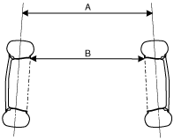
• Rim inner: B indicated in the figure (between the inner side of the rims)
FRONT WHEEL ALIGNMENT
id021100800200
Front wheel alignment (unloaded)*1 [ZJ, ZY, Z6, LF, L3, MZ-CD1.6 (Y6) and MZR-CD (RF Turbo)]
|
Item |
Fuel gauge indication |
||||||
|---|---|---|---|---|---|---|---|
|
Empty |
1/4 |
1/2 |
3/4 |
Full |
|||
|
Maximum steering angle
[Tolerance ±3°]
|
Inner
|
39°48′
|
|||||
|
Outer
|
32°48′
|
||||||
|
Total toe‐in
|
Tire
[Tolerance ±4 {±0.16}]
|
(mm {in})
|
2 {0.08}
|
||||
|
Rim inner
|
1±3 {0.04±0.12}
|
||||||
|
(degree)
|
0°11′±0°11′
|
||||||
|
Caster angle*2[Tolerance ±1°]
|
2°55′
|
2°57′
|
3°00′
|
3°02′
|
3°04′
|
||
|
Camber angle*2[Tolerance ±1°]
|
−0°39′
|
−0°39′
|
−0°40′
|
−0°41′
|
|||
|
Steering axis inclination (Reference value)
|
13°52′
|
13°53′
|
13°55′
|
||||
Front wheel alignment (unloaded)*1 [L3 Turbo]
|
Item |
Fuel gauge indication |
||||||
|---|---|---|---|---|---|---|---|
|
Empty |
1/4 |
1/2 |
3/4 |
Full |
|||
|
Maximum steering angle
[Tolerance ±3°]
|
Inner
|
36°00′
|
|||||
|
Outer
|
30°12′
|
||||||
|
Total toe‐in
|
Tire
[Tolerance ±4 {±0.16}]
|
(mm {in})
|
2 {0.08}
|
||||
|
Rim inner
|
1±3 {0.04±0.12}
|
||||||
|
(degree)
|
0°11′±0°11′
|
||||||
|
Caster angle*2[Tolerance ±1°]
|
3°00′
|
3°01′
|
3°03′
|
3°05′
|
3°07′
|
||
|
Camber angle*2[Tolerance ±1°]
|
−0°54′
|
−0°55′
|
−0°55′
|
||||
|
Steering axis inclination (Reference value)
|
14°17′
|
14°18′
|
|||||
am3zzw00002811
|
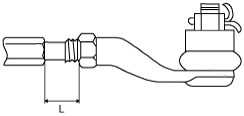
Steering Angle Adjustment
1. Loosen the locknut of the tie-rod end.
2. Remove the rack boot clamp.
3. Rotate the tie rod and adjust the steering angle.
4. Rotate the tie rod and adjust so that the length L shown in the figure is within the specification.
am3zzw00002812
|
5. Tighten the locknut of the tie-rod end.
6. Correct the rack boot twists.
7. Install and fix the rack boot clamp.
8. After adjusting the steering angle, always inspect and adjust the toe angle.
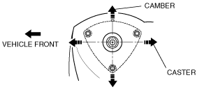
Camber and Caster Angle Adjustment
1. Remove the shock absorber upper bolts.
2. Move the shock absorber and coil spring to adjust the camber and caster angle.
am3zzw00002813
|
3. Install the shock absorber upper bolts.
4. Reinspect the alignment to make sure that it is within the specification.
Total Toe-in Adjustment
1. Loosen the locknut of the tie-rod end.
2. Remove the rack boot clamp.
3. Adjust the total toe-in by rotating each tie rod (left and right) in the opposite directions by the same amount respectively.
4. Tighten the locknut of the tie-rod end.
5. Verify that the rack boot does not have any twisting and install the rack boot clamp.