 |
am3zzw00009214
REAR TRAILING LINK REMOVAL/INSTALLATION
id021400802000
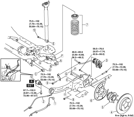
1. Remove in the order indicated in the table.
2. Install in the reverse order of removal.
3. Inspect the wheel alignment and adjust it if necessary. (See REAR WHEEL ALIGNMENT.)
am3zzw00009214
|
|
1
|
ABS wheel-speed sensor wiring harness connector
|
|
2
|
Parking brake cable
|
|
3
|
Brake caliper component
|
|
4
|
Disc plate
|
|
5
|
Rear hub component
|
|
6
|
Dust cover
|
|
7
|
Rear coil spring component
|
|
8
|
Rear lateral link outer bolt
|
|
9
|
Rear upper arm outer bolt
|
|
10
|
Rear shock absorber lower bolt
|
|
11
|
Rear trailing link
|
|
12
|
Bushing
(See Bushing Removal Note.)
(See Bushing Installation Note.)
|
Brake Caliper Component Removal Note
1. Hang the caliper component using a cable and move aside.
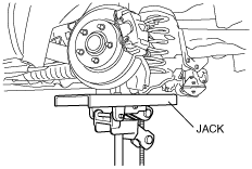
Rear Lateral Link Outer Bolt Removal Note
1. Support the trailing link using a jack.
am3zzw00002866
|
2. Remove the rear lateral link outer bolt.
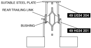
Bushing Removal Note
1. Remove the bushing using the SSTs.
am3zzw00009215
|
Rear Trailing Link Installation Note
1. Support the trailing link using a jack.
am3zzw00002866
|
2. Tighten the trailing link front side bolts.
Bushing Installation Note
1. Verify that there is no dirt on the bushing of the rear trailing link, and clean it if it has become soiled.
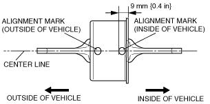
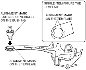
2. Place alignment marks (outside/inside of vehicle) on the center line of the bushing as shown in the figure.
am3zzw00009216
|
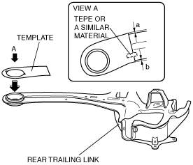
3. Set the template included in the packaging for the bushing to the rear trailing link using tape or a similar material as shown in the figure.
am3zzw00009217
|
4. Align the alignment mark on the template with the alignment mark (outside of vehicle) on the bushing as shown in the figure.
am3zzw00009218
|
5. Set the SSTs as shown in the figure.
am3zzw00009219
|
6. Press fit the bushing into the rear trailing link, and verify that the bushing is correctly installed as shown in the figure.
am3zzw00009220
|
7. If the bushing is not correctly installed, remove and re-install it.
8. Remove the template from the rear trailing link.