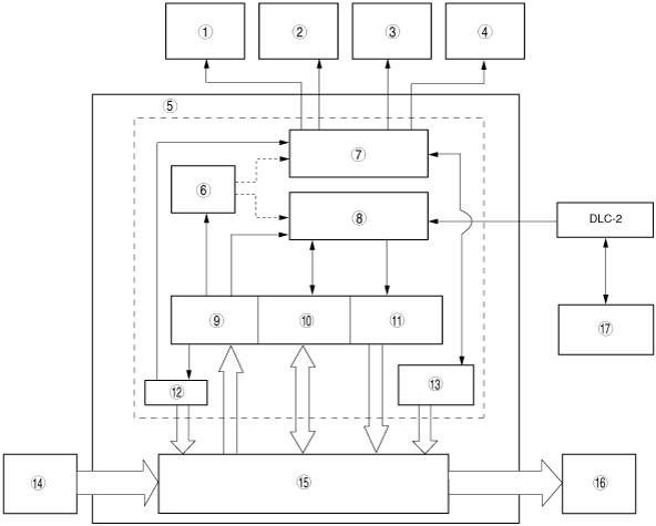
ON-BOARD DIAGNOSTIC SYSTEM OUTLINE[ABS, DYNAMIC STABILITY CONTROL (DSC)]


id0402b1100700

•  The on-board diagnostic system consists of a malfunction detection system that detects abnormalities in input/output signals when the ignition switch is at the ON position, a data monitor function that reads out specified input/output signals and a active command modes function that allows for override operation of output parts (such as solenoid valves).
•  The data link connector 2 (DLC-2), which groups together all the connectors used for malfunction diagnosis and detecting/repair into a single location, has been adopted, thereby improving serviceability. Diagnosis is performed by connecting the Mazda Modular Diagnostic System (M-MDS) to the DLC-2.
•  In addition to DTC read-out, the Mazda Modular Diagnostic System (M-MDS) is used to clear DTCs using the display screen of the diagnostic tester, and to access the PID/data monitor and active command modes functions, providing enhanced malfunction diagnosis and improved serviceability.

Block Diagram

am3zzn00000667

1
DSC indicator light (with DSC)
2
DSC OFF light (with DSC)
3
ABS warning light
4
Brake system warning light
5
On-board diagnostic function
6
Memory function
7
Malfunction display function
8
Serial communication
9
Malfunction detection function
10
PID/DATA monitor function
11
Active command modes function
12
Fail-safe function
13
HU inspection function
14
Input device
15
Normal control area
16
Output device
17
Mazda Modular Diagnostic System (M-MDS)