 |
am3zzw00003159
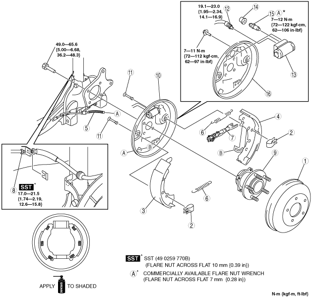
REAR BRAKE (DRUM) REMOVAL/INSTALLATION
id041100810100
1. Disconnect the rear ABS wheel-speed sensor connector.
2. Remove in the order indicated in the table.
3. Install in the reverse order of removal.
4. After installation, pump the brake pedal a few times and inspect the following:
am3zzw00003159
|
|
1
|
Brake drum
|
|
2
|
Hold spring
|
|
3
|
Leading shoe
|
|
4
|
Trailing shoe
|
|
5
|
End cable
|
|
6
|
Shoe return spring
|
|
7
|
Adjuster
(See Adjuster Installation Note.)
|
|
8
|
Brake pipe
|
|
9
|
Wheel hub component
|
|
10
|
Backing plate, wheel cylinder, brake Hose
|
|
11
|
Hold pin
|
|
12
|
Brake hose
|
|
13
|
Wheel cylinder
|
|
14
|
Bleeder cap
|
|
15
|
Bleeder screw
|
|
16
|
Backing plate
|
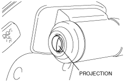
Wheel Cylinder Installation Note
1. Install the wheel cylinder to the backing plate with the part of the piston that contacts the brake shoe in the direction shown in the figure (projection facing outward).
am3zzw00003160
|
Backing Plate, Wheel Cylinder, Brake Hose, and Wheel Hub Component Installation Note
1. Verify that the hold pin is installed to the backing plate.
2. Install the backing plate, wheel cylinder, brake hose, and wheel hub component to the trailing link.
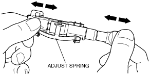
Adjuster Installation Note
1. Before installing the adjuster, verify that the adjusting function operates properly by pressing the ends of the adjuster inward a few times.
am3zzw00003161
|
2. Install the adjuster in the direction shown in the figure.
am3zzw00003162
|
Hold Spring (Trailing Shoe Side) Installation Note
1. Insert a flathead screwdriver into the trailing link hole from the vehicle side and press the hold pin.
2. Install the hold spring (trailing shoe side) to the hold pin.