ABS CONTROL OUTLINE
id041300184200
Feature
• ABS control occurs when wheel slip is determined by the ABS CM (based on the four ABS wheel-speed sensors). Then, the ABS HU inlet and outlet solenoid valves are operated and brake fluid pressure is controlled accordingly to prevent wheel lock-up.
• Use of ABS control during emergency braking or on slippery road surfaces allows directional stability to be maintained, steerability ensured and stopping distance to be reduced.
• The ABS control system has independent front wheel control and unified control (select low) for the rear wheels.
-
Note
-
• Select low control: A control system in which the left and right vehicle wheel speeds are compared and brake fluid pressure is controlled according to the wheel most likely to lock-up.
STRUCTURE
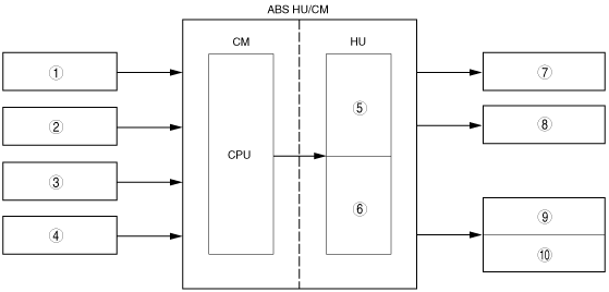
Block Diagram
|
1
|
ABS wheel-speed sensor (LF)
|
|
2
|
ABS wheel-speed sensor (RF)
|
|
3
|
ABS wheel-speed sensor (LR)
|
|
4
|
ABS wheel-speed sensor (RR)
|
|
5
|
Solenoid valve
|
|
6
|
Pump motor
|
|
7
|
Caliper piston (LF)
|
|
8
|
Caliper piston (RF)
|
|
9
|
Caliper piston (LR)
|
|
10
|
Caliper piston (RR)
|