 |
b3e0415t013
DSC HU PART CONSTRUCTION/OPERATION
id041500100900
Construction
Function Of Main Component Parts
|
Part name |
Function |
|---|---|
|
Inlet solenoid valve
|
• Adjusts the fluid pressure in each brake system according to DSC HU/CM signals.
|
|
Outlet solenoid valve
|
• Adjusts the fluid pressure in each brake system according to DSC HU/CM signals.
|
|
Stability control solenoid valve
|
• Switches the brake hydraulic circuits during and according to normal braking, ABS and EBD control, TCS control and DSC control.
|
|
Traction control solenoid valve
|
• Switches the brake hydraulic circuits during and according to normal braking, ABS and EBD control, TCS control and DSC control.
|
|
Reservoir
|
• Temporarily stores brake fluid from the caliper piston to ensure smooth pressure reduction during ABS and EBD control, TCS control and DSC control.
|
|
Pump
|
• Returns the brake fluid stored in the reservoir to the master cylinder during ABS and DSC control.
• Increases brake fluid pressure and sends brake fluid to each caliper piston during TCS control and DSC control.
|
|
Pump motor
|
• Operates the pump according to DSC HU/CM signals.
|
|
Flow control valve
|
• Shifts fluid flow from constricted paths during pressure reduce mode to suppress noise. (Only installed on the front system.)
|
b3e0415t013
|
|
1
|
Master cylinder
|
|
2
|
Brake fluid pressure sensor
|
|
3
|
Damper chamber
|
|
4
|
Reservoir
|
|
5
|
Pump motor
|
|
6
|
Pump
|
|
7
|
Check valve
|
|
8
|
Traction control solenoid valve
|
|
9
|
Stability control solenoid valve
|
|
10
|
Inlet solenoid valve
|
|
11
|
Outlet solenoid valve
|
|
12
|
Flow control valve
|
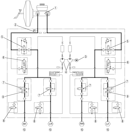
Operation
During normal braking
Solenoid valve operation table
|
Traction control solenoid valve |
Stability control solenoid valve |
Inlet side Solenoid valve |
Outlet side Solenoid valve |
Pump motor, pump |
||||||||
|---|---|---|---|---|---|---|---|---|---|---|---|---|
|
LF―RR |
RF―LR |
LF―RR |
RF―LR |
LF |
RF |
LR |
RR |
LF |
RF |
LR |
RR |
|
|
OFF (open)
|
OFF (closed)
|
OFF (open)
|
OFF (closed)
|
Stopped
|
||||||||
Hydraulic Circuit Diagram
b3e0415t014
|
|
1
|
Master cylinder
|
|
2
|
Brake fluid pressure sensor
|
|
3
|
Pump motor
|
|
4
|
Pump
|
|
5
|
Traction control solenoid valve
|
|
6
|
Stability control solenoid valve
|
|
7
|
Inlet solenoid valve
|
|
8
|
Outlet solenoid valve
|
|
9
|
Flow control valve
|
|
10
|
Pressure increase
|
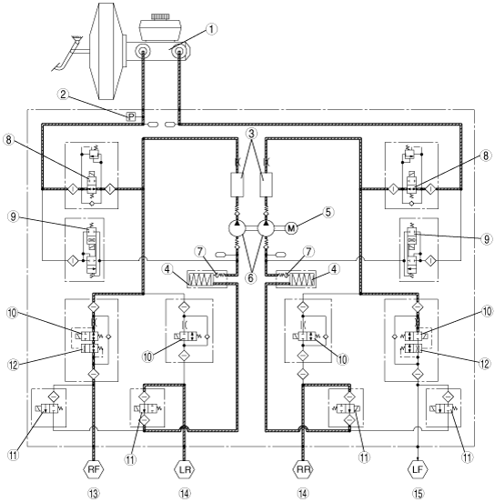
During ABS and EBD control
Solenoid valve operation table
|
|
Traction control solenoid valve |
Stability control solenoid valve |
Inlet side Solenoid valve |
Outlet side solenoid valve |
Pump motor, pump |
||||||||
|---|---|---|---|---|---|---|---|---|---|---|---|---|---|
|
LF―RR |
RF―LR |
LF―RR |
RF―LR |
LF |
RF |
LR |
RR |
LF |
RF |
LR |
RR |
||
|
During pressure increase mode
|
OFF (open)
|
OFF (closed)
|
OFF (open)
|
OFF (closed)
|
Stopped
|
||||||||
|
During pressure maintain mode
|
OFF (open)
|
OFF (closed)
|
ON (closed)
|
OFF (closed)
|
Stopped
|
||||||||
|
During pressure reduction mode
|
OFF (open)
|
OFF (closed)
|
ON (closed)
|
ON (open)
|
Operating
|
||||||||
Hydraulic Circuit Diagram
b3e0415t015
|
|
1
|
Master cylinder
|
|
2
|
Brake fluid pressure sensor
|
|
3
|
Damper chamber
|
|
4
|
Reservoir
|
|
5
|
Pump motor
|
|
6
|
Pump
|
|
7
|
Check valve
|
|
8
|
Traction control solenoid valve
|
|
9
|
Stability control solenoid valve
|
|
10
|
Inlet solenoid valve
|
|
11
|
Outlet solenoid valve
|
|
12
|
Flow control valve
|
|
13
|
Pressure increase
|
|
14
|
Pressure reduction
|
|
15
|
Pressure maintained
|
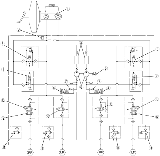
During DSC control (to suppress oversteer tendency) and TCS control
Solenoid valve operation table
|
|
Traction control solenoid valve |
Stability control solenoid valve |
Inlet solenoid valve |
Outlet solenoid valve |
Pump motor, pump |
||||||||
|---|---|---|---|---|---|---|---|---|---|---|---|---|---|
|
LF―RR |
RF―LR |
LF―RR |
RF―LR |
LF |
RF |
LR |
RR |
LF |
RF |
LR |
RR |
||
|
During pressure increase mode
|
OFF
(open)
|
ON
(closed)
|
OFF (closed)
|
ON
(open)
|
OFF
(open)
|
ON
(closed)
|
OFF
(open)
|
OFF (closed)
|
Operating
|
||||
|
During pressure maintain mode
|
OFF
(open)
|
ON
(closed)
|
OFF (closed)
|
OFF
(open)
|
ON
(closed)
|
OFF
(open)
|
OFF (closed)
|
Stopped
|
|||||
|
During pressure reduction mode
|
OFF
(open)
|
ON
(closed)
|
OFF (closed)
|
OFF
(open)
|
ON
(closed)
|
OFF
(open)
|
OFF
(closed)
|
ON
(open)
|
OFF
(closed)
|
Operating
|
|||
Hydraulic Circuit Diagram
b3e0415t016
|
|
1
|
Master cylinder
|
|
2
|
Brake fluid pressure sensor
|
|
3
|
Damper chamber
|
|
4
|
Reservoir
|
|
5
|
Pump motor
|
|
6
|
Pump
|
|
7
|
Check valve
|
|
8
|
Traction control solenoid valve
|
|
9
|
Stability control solenoid valve
|
|
10
|
Inlet solenoid valve
|
|
11
|
Outlet solenoid valve
|
|
12
|
Flow control valve
|
|
13
|
Pressure increase
|
During DSC control (to suppress understeer tendency)
Solenoid valve operation table
|
|
Traction control solenoid valve |
Stability control solenoid valve |
Inlet solenoid valve |
Outlet solenoid valve |
Pump motor, pump, |
||||||||
|---|---|---|---|---|---|---|---|---|---|---|---|---|---|
|
LF―RR |
RF―LR |
LF―RR |
RF―LR |
LF |
RF |
LR |
RR |
LF |
RF |
LR |
RR |
||
|
During pressure increase mode
|
OFF
(open)
|
ON
(closed)
|
OFF
(closed)
|
ON
(open)
|
OFF
(open)
|
ON
(closed)
|
OFF
(open)
|
OFF (closed)
|
Operating
|
||||
|
During pressure maintain mode
|
OFF
(open)
|
ON
(closed)
|
OFF (closed)
|
OFF
(open)
|
ON
(closed)
|
OFF
(open)
|
OFF (closed)
|
Stopped
|
|||||
|
During pressure reduction mode
|
OFF
(open)
|
ON
(closed)
|
OFF (closed)
|
OFF
(open)
|
ON
(closed)
|
OFF
(open)
|
OFF
(closed)
|
ON
(open)
|
OFF
(closed)
|
Operating
|
|||
Hydraulic Circuit Diagram
b3e0415t017
|
|
1
|
Master cylinder
|
|
2
|
Brake fluid pressure sensor
|
|
3
|
Damper chamber
|
|
4
|
Reservoir
|
|
5
|
Pump motor
|
|
6
|
Pump
|
|
7
|
Check valve
|
|
8
|
Traction control solenoid valve
|
|
9
|
Stability control solenoid valve
|
|
10
|
Inlet solenoid valve
|
|
11
|
Outlet solenoid valve
|
|
12
|
Flow control valve
|
|
13
|
Pressure increase
|