TORQUE CONVERTER CLUTCH (TCC) CONTROL OUTLINE[FN4A-EL]
id051701108600
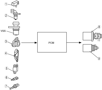
• The PCM selects and determines the TCC diagram based on the shift control results. With this TCC diagram, and according to the signals from VSS, TP sensor [Z6], APP semsor [ZY, LF], and other switches and sensors, the PCM sends the signal to the duty-cycle type shift solenoids A and on/off type shift solenoid E to operate TCC control.
• Smooth TCC control, which engages the TCC gradually, has been adopted to reduce the shock when the TCC engages.
|
1
|
TFT sensor
|
|
2
|
Input/turbine speed sensor
|
|
3
|
TP sensor [Z6]
|
|
4
|
APP sensor [ZY, LF]
|
|
5
|
CKP sensor
|
|
6
|
Brake switch
|
|
7
|
ECT sensor
|
|
8
|
Shift solenoid A
|
|
9
|
Shift solenoid E
|