 |
am3zzn00001078
MANUAL MODE SHIFT CONTROL OPERATION [FS5A-EL]
id051721102800
Manual mode shift
|
Condition |
Shift control |
Note |
|---|---|---|
|
2GR→3GR up-shift command at low speed
|
• To reduce load on the ATX, upshifting is inhibited until vehicle reaches speed possible for upshifting
|
—
|
|
3GR→4GR up-shift command at low speed
|
||
|
4GR→5GR up-shift command at low speed
|
||
|
4GR→5GR up-shift command, low ATF temperature
|
• To reduce load on the ATX, upshifting to 5GR is inhibited
|
|
|
5GR→4GR down-shift command, above set speed
|
• To prevent engine over-rev, downshifting is inhibited until vehicle reaches speed possible for downshifting
|
• Gear position indicator light flash to alert driver
|
|
4GR→3GR down-shift command, above set speed
|
||
|
3GR→2GR down-shift command, above set speed
|
||
|
2GR→1GR down-shift command, above set speed
|
||
|
In 5GR deceleration, speed goes below coast-down set speed (deceleration down- shift)
|
• To assure drive stability, automatically downshifts from 5GR to 3GR
|
—
|
|
In 4GR deceleration, speed goes below coast-down set speed (deceleration down- shift)
|
• To assure drive stability, automatically downshifts from 4GR to 3GR
|
|
|
In 3GR deceleration, speed goes below coast-down set speed (deceleration down- shift)
|
• To assure drive stability, automatically downshifts from 3GR to 1GR
|
|
|
In 2GR deceleration, speed goes below coast-down set speed (deceleration down- shift)
|
• To assure drive stability, automatically downshifts from 2GR to 1GR
|
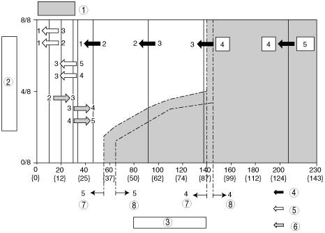
Shift diagram
am3zzn00001078
|
|
1
|
TCC operation available
|
|
2
|
Throttle opening
|
|
3
|
Vehicle speed km/h {mph}
|
|
4
|
Downshifting is inhibited until vehicle reaches speed possible for downshifting
|
|
5
|
When decelerating below set vehicle speed, executes automatic downshifting
|
|
6
|
Upshifting is inhibited until vehicle reaches speed possible for upshifting
|
|
7
|
TCC off
|
|
8
|
TCC on
|