|
am3zzw00003441
TRANSAXLE RANGE (TR) SWITCH REMOVAL/INSTALLATION[FS5A-EL]
id051721804000
1. Remove the battery duct and battery cover. (See BATTERY REMOVAL/INSTALLATION[LF, L3].)
2. Disconnect the negative battery cable.
3. Remove the under cover.
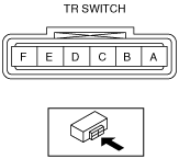
4. Disconnect the TR switch connector.
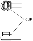
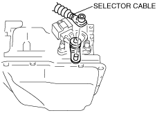
5. Remove the clip and disconnect the selector cable.
am3zzw00003441
|
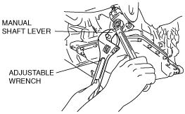
6. Set the adjustable wrench as shown in the figure to hold the manual shaft lever.
am3zzw00003442
|
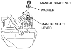
7. Remove the manual shaft nut and washer.
8. Remove the manual shaft lever.
am3zzw00003443
|
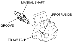
9. Remove the TR switch.
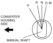
10. Rotate the manual shaft to the converter housing side fully, then return two notches to set the N position.
am3zzw00003566
|
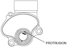
11. Turn the protrusion between the TR switch terminals B and C until the resistance becomes 750 ohms.
am3zzw00003444
|
am3zzw00003445
|
12. Install the TR switch while aligning the protrusion and groove as shown in the figure.
am3zzw00003446
|
13. Hand-tighten the TR switch mounting bolts.
14. Inspect the resistance between the TR switch terminals B and C.
am3zzw00003445
|
15. Tighten the TR switch mounting bolts.
16. Install the manual shaft lever and the washer.
am3zzw00003443
|
17. Set the adjustable wrench as shown in the figure to hold the manual shaft lever, and tighten the manual shaft nut.
am3zzw00003447
|
18. Install the clip to the selector cable as shown in the figure.
am3zzw00003448
|
19. Shift the selector lever to P position.
20. Turn the manual shaft lever to P position.
21. Connect the selector cable.
am3zzw00003449
|
22. Inspect for continuity at the TR switch. (See TRANSAXLE RANGE (TR) SWITCH INSPECTION[FS5A-EL].)
23. Connect the TR switch connector.
24. Install the under cover.
25. Connect the negative battery cable.
26. Install the battery duct and battery cover. (See BATTERY REMOVAL/INSTALLATION[LF, L3].)
27. Inspect operation of the TR switch. (See TRANSAXLE RANGE (TR) SWITCH INSPECTION[FS5A-EL].)