 |
am3zzw00003578
SOLENOID VALVE INSPECTION (PRIMARY CONTROL VALVE BODY)[FS5A-EL]
id051721807700
Resistance Inspection (On-Vehicle Inspection)
1. Remove the battery duct and battery cover. (See BATTERY REMOVAL/INSTALLATION[LF, L3].)
2. Disconnect the negative battery cable.
3. Remove the air cleaner component. (See INTAKE AIR SYSTEM REMOVAL/INSTALLATION[LF, L3].)
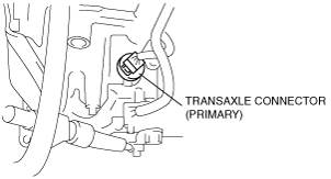
4. Disconnect the transaxle connector (primary).
am3zzw00003578
|
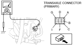
5. Measure the resistance between the following terminals.
am3zzw00003579
|
Primary control valve body (ATF temperature: –40—150 °C {–40—302 °F})
|
Terminal |
Solenoid valve |
Resistance (ohm) |
|---|---|---|
|
A—GND
|
Shift solenoid A
|
1.0—4.2
|
|
C—GND
|
Shift solenoid B
|
1.0—4.2
|
|
G—GND
|
Shift solenoid C
|
1.0—4.2
|
|
B—GND
|
Shift solenoid D
|
10.9—26.2
|
|
F—GND
|
Shift solenoid E
|
10.9—26.2
|
|
D—I
|
Pressure control solenoid A
|
2.4—7.3
|
6. Connect the transaxle connector (primary).
7. Install the air cleaner component. (See INTAKE AIR SYSTEM REMOVAL/INSTALLATION[LF, L3].)
8. Connect the negative battery cable.
9. Install the battery duct and battery cover. (See BATTERY REMOVAL/INSTALLATION[LF, L3].)
Operating Inspection
1. Disconnect the transaxle connector (primary).
2. Apply battery positive voltage to terminals A,B,C, F or G and battery negative voltage to GND, and verify that operating sound is heard from solenoid.
3. Apply battery positive voltage to terminal D and battery negative voltage to terminal I, and verify that operating sound is heard from solenoid.
am3zzw00003580
|
Resistance Inspection (Off‐Vehicle Inspection)
1. Remove the battery duct and battery cover. (See BATTERY REMOVAL/INSTALLATION[LF, L3].)
2. Disconnect the negative battery cable.
3. Remove the solenoid valve(s). (See SOLENOID VALVE REMOVAL/INSTALLATION (PRIMARY CONTROL VALVE BODY)[FS5A-EL].)
4. Measure the resistance of each solenoid valve individually.
5. Install the solenoid valve(s). (See SOLENOID VALVE REMOVAL/INSTALLATION (PRIMARY CONTROL VALVE BODY)[FS5A-EL].)
6. Connect the negative battery cable.
7. Install the battery duct and battery cover. (See BATTERY REMOVAL/INSTALLATION[LF, L3].)
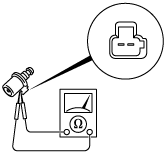
Pressure control solenoid A
am3zzw00003457
|
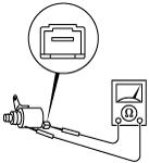
Shift solenoid A, B, C
am3zzw00003458
|
Shift solenoid D, E
ampjjw00001463
|