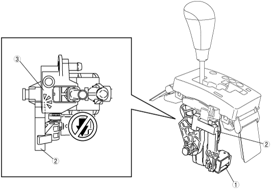
SHIFT-LOCK SYSTEM STRUCTURE


id051800101100


Structure

•  The shift-lock system consists of the PJB (shift-lock relay), brake switch, shift-lock solenoid, and selector lever component.
am3zzn00000524

1
PJB (shift-lock relay)
2
Brake switch
3
Selector lever component
4
Shift-lock solenoid
5
P position switch
6
P position
7
Except P position
8
To key interlock solenoid


Operation


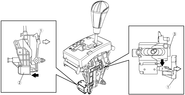
Shift-lock release condition

•  The shift-lock is released when the selector lever at P position, ignition switch is at ON position and the brake pedal is depressed.


Shift-lock (when the shift-lock conditions are not satisfied)

•  When the shift-lock conditions are not satisfied, electrical current does not flow to the shift-lock solenoid from the shift-lock relay. The lock lever therefore mechanically restricts the movement of the selector lever, preventing shifting out of Park.

L.H.D.

am3zzn00000525

R.H.D.

am3zzn00000526

1
Shift-lock solenoid
2
Lock lever
3
Selector lever


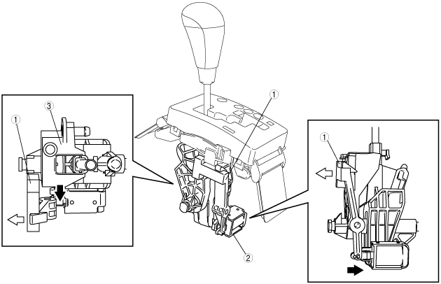
Shift-lock release (when the shift-lock conditions are satisfied)

•  When the shift-lock conditions are satisfied, electrical current flows to the shift-lock solenoid from the shift-lock relay. The slider therefore moves toward the shift-lock solenoid and the lock lever moves to a position in which it does not restrict movement of the selector lever, allowing shifting out of Park.

L.H.D.

am3zzn00000527

R.H.D.

am3zzn00000528

1
Lock lever
2
Shift-lock solenoid
3
Selector lever


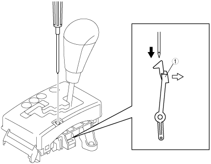
Shift-lock release (when inserting a screwdriver into the shift-lock release hole.)

•  A screwdriver can be inserted into the shift-lock release hole, and then pressed against the slanted part of the lock lever to open it outward. Due to this, the selector lever is not restricted by the lock lever and the shift lock is released.

L.H.D.

am3zzn00000529

R.H.D.

am3zzn00001395

1
Lock lever