 |
am3zzn00000441
A/C UNIT CONSTRUCTION/OPERATION
id071100100400
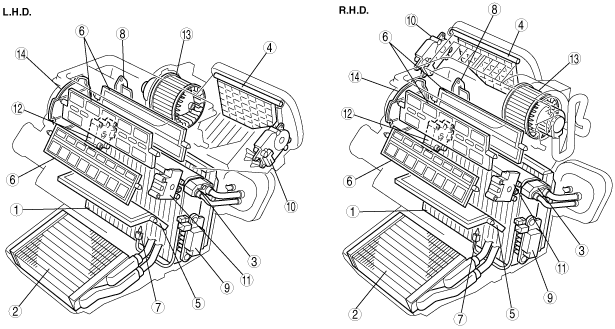
Construction
am3zzn00000441
|
|
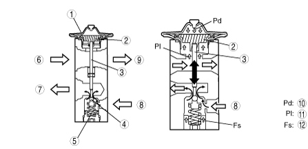
1
|
Evaporator
|
|
2
|
Heater core
|
|
3
|
Expansion valve
|
|
4
|
Air intake door
|
|
5
|
Air mix door
|
|
6
|
Airflow mode door
|
|
7
|
Evaporator temperature sensor
|
|
8
|
Resistor (manual air conditioner)
|
|
9
|
Power MOS FET (full-auto air conditioner)
|
|
10
|
Air intake actuator (except Australian, General (L.H.D. R.H.D.) specs. manual air conditioner)
|
|
11
|
Air mix actuator (full-auto air conditioner)
|
|
12
|
Airflow mode actuator (full-auto air conditioner)
|
|
13
|
Blower motor
|
|
14
|
Airflow mode main link
|
Evaporator
am3zzn00000442
|
|
1
|
Separation part
|
|
2
|
Rejoining point
|
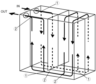
Expansion valve
am3zzn00000443
|
|
1
|
Diaphragm
|
|
2
|
Temperature sensor
|
|
3
|
Shaft
|
|
4
|
Ball valve
|
|
5
|
Spring
|
|
6
|
From evaporator
|
|
7
|
To evaporator
|
|
8
|
From condenser
|
|
9
|
To A/C compressor
|
|
10
|
Pressure diaphragm
|
|
11
|
Pressure low
|
|
12
|
Force spring
|
Operation
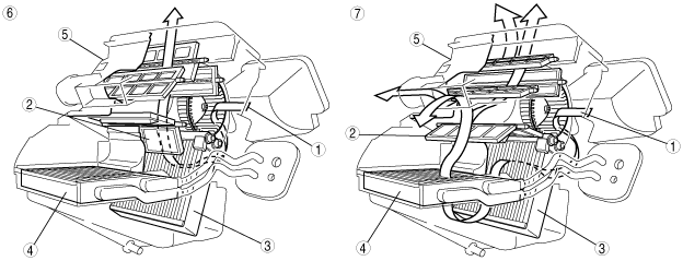
Air Mix Door Operation
L.H.D.
am3zzn00000444
|
R.H.D.
am3zzn00000445
|
|
1
|
Airflow
|
|
2
|
Air mix door
|
|
3
|
Evaporator
|
|
4
|
Heater core
|
|
5
|
A/C unit
|
|
6
|
COLD
|
|
7
|
HOT
|
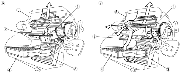
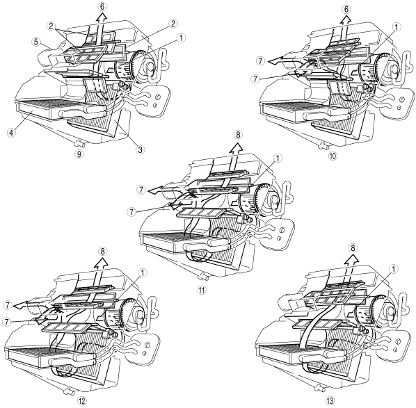
Airflow Mode Door Operation
L.H.D.
am3zzn00001480
|
R.H.D.
am3zzn00000447
|
|
1
|
Airflow
|
|
2
|
Airflow mode door
|
|
3
|
Evaporator
|
|
4
|
Heater core
|
|
5
|
A/C unit
|
|
6
|
To center, side vent
|
|
7
|
To front and rear heat
|
|
8
|
To defroster and side demister
|
|
9
|
VENT
|
|
10
|
BI-LEVEL
|
|
11
|
HEAT
|
|
12
|
HEAT/DEF
|
|
13
|
DEFROSTER
|