 |
am3zzn00000473
MANUAL AIR CONDITIONER CONTROL SYSTEM
id074000101000
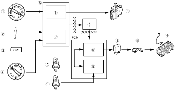
Block Diagram
am3zzn00000473
|
|
1
|
Airflow mode selector switch (European (L.H.D. U.K.) specs.)
|
|
2
|
Evaporator temperature sensor
|
|
3
|
A/C switch
|
|
4
|
Airflow volume control dial
|
|
5
|
Climate control unit
|
|
6
|
Defroster control (European (L.H.D. U.K.) specs.)
|
|
7
|
A/C compressor control
|
|
8
|
Air intake actuator (European (L.H.D. U.K.) specs.)
|
|
9
|
PJB and instrument cluster
|
|
10
|
Refrigerant pressure switch (HI and LO pressure)
|
|
11
|
Refrigerant pressure switch (medium pressure)
|
|
12
|
A/C cut-off control
|
|
13
|
Idle air control
|
|
14
|
A/C relay
|
|
15
|
Stator and thermal protector
|
|
16
|
Magnetic clutch
|
Outline of Control System
|
Control name |
Control part |
|---|---|
|
Defroster control (European (L.H.D. U.K.) specs.)
|
Climate control unit
|
|
A/C compressor control
|
Climate control unit
|
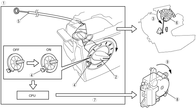
Defroster Control(European (L.H.D. U.K.) specs.)
1. When the airflow mode selector dial is turned to DEFROSTER position, a wire moves the airflow mode main link, turning the airflow mode to DEFROSTER.
2. The defroster switch turns on at the same time, and the CPU sends a signal to turn the air intake mode to FRESH.
3. The air intake actuator operates and turns the air intake mode to FRESH.
am3zzn00000474
|
|
1
|
Climate control unit
|
|
2
|
Airflow mode selector dial
|
|
3
|
To DEFROSTER position
|
|
4
|
Defroster switch
|
|
5
|
Wire
|
|
6
|
Airflow mode main link
|
|
7
|
FRESH signal
|
|
8
|
Air intake actuator
|
|
9
|
To FRESH position
|
|
Airflow mode |
Air intake mode (REC switch pushed) |
Defroster control |
|---|---|---|
|
VENT
|
REC Û FRESH
|
–
|
|
BI-LEVEL
|
REC Û FRESH
|
–
|
|
HEAT
|
REC Û FRESH
|
–
|
|
HEAT/DEF
|
REC Û FRESH
|
–
|
|
DEFROSTER
|
FRESH
|
x
|
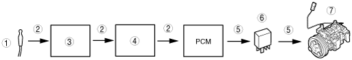
A/C Compressor Control
am3zzn00000475
|
|
1
|
Evaporator temperature sensor
|
|
2
|
A/C signal
|
|
3
|
Climate control unit
|
|
4
|
PJB and instrument cluster
|
|
5
|
Output
|
|
6
|
A/C relay
|
|
7
|
Magnetic clutch
|
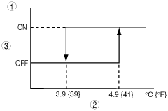
A/C signal on/off control
am3zzn00000476
|
|
1
|
A/C signal on/off decision
|
|
2
|
Evaporator temperature sensor
|
|
3
|
A/C signal
|