 |
am3zzn00000575
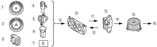
AIRFLOW VOLUME CONTROL SYSTEM DIAGRAM
id074000102500
am3zzn00000575
|
|
1
|
Airflow volume
|
|
2
|
Set temperature
|
|
3
|
Airflow mode
|
|
4
|
Ambient temperature
|
|
5
|
Cabin temperature
|
|
6
|
Solar radiation amount
|
|
7
|
Engine coolant temperature
|
|
8
|
ECT sensor
|
|
9
|
Signal
|
|
10
|
Climate control unit
|
|
11
|
Output
|
|
12
|
Feedback
|
|
13
|
Power MOS FET
|
|
14
|
Operation
|
|
15
|
Blower motor
|
|
16
|
Airflow volume change
|