|
am3zzw00000864
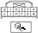
CLIMATE CONTROL UNIT INSPECTION [MANUAL AIR CONDITIONER]
id0740a2802200
1. Install the PJB.
2. Turn the ignition switch to the ON position.
3. Connect the negative (-) lead of the tester to body ground.
4. By inserting the positive (+) lead of the tester into each climate control unit terminal, measure the voltage according to the terminal voltage table.
Terminal Voltage Table (Reference)
European (L.H.D. U.K.) specs.
am3zzw00000864
|
|
Terminal |
Signal name |
Connected to |
Measurement condition |
Voltage (V) |
Inspection item (s) |
|---|---|---|---|---|---|
|
A
|
—
|
—
|
—
|
—
|
—
|
|
B
|
—
|
—
|
—
|
—
|
—
|
|
C
|
—
|
—
|
—
|
—
|
—
|
|
D
|
B+
|
ROOM 15 A fuse
|
Under any condition
|
B+
|
• Wiring harness: continuity, short circuit (Climate control unit— fuse: D—ROOM 15 A)
• ROOM 15 A fuse
|
|
E
|
—
|
—
|
—
|
—
|
—
|
|
F
|
IG2
|
A/C 10 A fuse
|
IG SW ON
|
B+
|
• Wiring harness: continuity, short circuit (Climate control unit— fuse: F—A/C 10 A)
• A/C 10 A fuse
|
|
IG SW LOCK
|
1.0 or less
|
• Wiring harness: continuity, short circuit (Climate control unit— fuse: F—A/C 10 A)
|
|||
|
G
|
—
|
—
|
—
|
—
|
—
|
|
H
|
—
|
—
|
—
|
—
|
—
|
|
I
|
—
|
—
|
—
|
—
|
—
|
|
J
|
GND
|
Body ground
|
Under any condition
|
1.0 or less
|
• Wiring harness: continuity (Climate control unit—GND: J—GND)
|
|
K
|
—
|
—
|
—
|
—
|
—
|
|
L
|
Sensor GND
|
Evaporator temperature sensor
|
Under any condition
|
1.0 or less
|
• Climate control unit: terminal voltage (J)
|
|
M
|
A/C
|
PJB
|
A/C switch ON, airflow volume control dial at 1st
|
1.0 or less
|
• Wiring harness: continuity (Climate control unit—PJB: M—J-04 AF)
|
|
A/C switch OFF
|
B+
|
• Wiring harness: continuity, short circuit (Climate control unit—PJB: M—J-04 AF)
|
|||
|
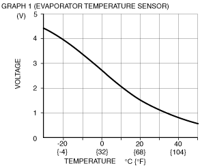
N
|
Evaporator temperature sensor input
|
Evaporator temperature sensor
|
Compared with temperature detected by evaporator temperature sensor
|
Refer to graph 1
|
• Wiring harness: continuity (Climate control unit—evaporator temperature sensor: N—B, L—A)
• Wiring harness: short circuit (Climate control unit—evaporator temperature sensor: N—B)
• Evaporator temperature sensor
• Climate control unit: terminal voltage (F, J)
|
|
O
|
Motor operation
|
Air intake actuator
|
Switched to RECIRCULATE
|
1.0 or less
|
• Wiring harness: continuity, short circuit (Climate control unit—air intake actuator: S—G, O—E)
• Air intake actuator
|
|
Switched to FRESH
|
12
|
||||
|
P
|
Rear window defroster switch indicator light
|
PJB
|
Rear window defroster switch ON
|
1.0 or less
|
• Wiring harness: continuity (Climate control unit—PJB: P—J-04 I)
• PJB
|
|
Rear window defroster switch OFF
|
4.0
|
• Wiring harness: short circuit (Climate control unit—PJB: P—J-04 I)
• PJB
|
|||
|
Q
|
Motor operation
|
Air intake actuator
|
Switched to RECIRCULATE
|
12
|
• Wiring harness: continuity, short circuit (Climate control unit—air intake actuator: Q—C, S—G)
• Air intake actuator
|
|
Switched to FRESH
|
1.0 or less
|
||||
|
R
|
Rear window defroster switch
|
PJB
|
Rear window defroster switch is pressed
|
1.0 or less
|
• Climate control unit: terminal voltage (J)
|
|
Rear window defroster switch is released
|
B+
|
• Wiring harness: open circuit, short circuit (Climate control unit—PJB: R—J-04 AD)
• PJB
|
|||
|
S
|
Motor operation
|
Air intake actuator
|
Switched to RECIRCULATE
|
12
|
• Wiring harness: continuity, short circuit (Climate control unit—air intake actuator: S—G, O—E, Q—C)
• Air intake actuator
|
|
Switched to FRESH
|
1.0 or less
|
||||
|
T
|
FAN signal
|
Fan switch
|
Fan switch ON
|
1.0 or less
|
• Wiring harness: continuity (Climate control unit—fan switch: T—A)
• Fan switch
|
|
Fan switch OFF
|
4.4
|
• Wiring harness: continuity (Climate control unit—fan switch: T—A)
• Climate control unit: terminal voltage (F)
• Fan switch
|
|||
|
U
|
TNS signal
|
Panel light control switch
|
Headlight switch OFF
|
1.0 or less
|
• Wiring harness: continuity (Climate control unit—panel light control switch: U—F)
• Panel light control switch
• Climate control unit: terminal voltage (V)
|
|
Headlight switch ON
|
12
|
• Wiring harness: short circuit (Climate control unit—panel light control switch: U—F)
|
|||
|
V
|
TNS signal
|
PJB
|
Headlight switch OFF
|
1.0 or less
|
• Wiring harness: short circuit (Climate control unit—PJB: V—J-03 H)
• PJB
• Headlight switch
|
|
Headlight switch ON
|
B+
|
• Wiring harness: continuity, short circuit (Climate control unit—PJB: V—J-03 H)
• PJB
• Headlight switch
|
|||
|
W
|
—
|
—
|
—
|
—
|
—
|
|
X
|
—
|
—
|
—
|
—
|
—
|
 |
–
|
Terminal Voltage Table (Reference)
Australian, General (L.H.D. R.H.D.) specs.
am3zzw00003277
|
|
Terminal |
Signal name |
Connected to |
Measurement condition |
Voltage (V) |
Inspection item (s) |
|---|---|---|---|---|---|
|
A
|
Evaporator temperature sensor input
|
Evaporator temperature sensor
|
Compared with temperature detected by evaporator temperature sensor
|
Refer to graph 1
|
• Wiring harness: continuity (Climate control unit—evaporator temperature sensor: A—B, B—A)
• Wiring harness: short circuit (Climate control unit—evaporator temperature sensor: A—B)
• Evaporator temperature sensor
• Climate control unit: terminal voltage (E, K)
|
|
B
|
Sensor GND
|
Evaporator temperature sensor
|
Under any condition
|
1.0 or less
|
• Climate control unit: terminal voltage (E)
|
|
C
|
A/C
|
PJB
|
A/C switch ON, airflow volume control dial at 1st
|
1.0 or less
|
• Wiring harness: continuity (Climate control unit—PJB: C—J-04 AF)
|
|
A/C switch OFF
|
B+
|
• Wiring harness: continuity, short circuit (Climate control unit—PJB: C—J-04 AF)
|
|||
|
D
|
TNS signal
|
Panel light control switch
|
Headlight switch OFF
|
1.0 or less
|
• Wiring harness: continuity (Climate control unit—panel light control switch: D—F)
• Panel light control switch
• Climate control unit: terminal voltage (V)
|
|
Headlight switch ON
|
12
|
• Wiring harness: short circuit (Climate control unit—panel light control switch: D—F)
|
|||
|
E
|
GND
|
Body ground
|
Under any condition
|
1.0 or less
|
• Wiring harness: continuity (Climate control unit—GND: E—GND)
|
|
F
|
FAN signal
|
Fan switch
|
Fan switch ON
|
1.0 or less
|
• Wiring harness: continuity (Climate control unit—fan switch: F—A)
• Fan switch
|
|
Fan switch OFF
|
4.4
|
• Wiring harness: continuity (Climate control unit—fan switch: F—A)
• Climate control unit: terminal voltage (K)
• Fan switch
|
|||
|
G
|
Rear window defroster switch indicator light
|
PJB
|
Rear window defroster switch ON
|
1.0 or less
|
• Wiring harness: continuity (Climate control unit—PJB: G—J-04 I)
• PJB
|
|
Rear window defroster switch OFF
|
4.0
|
• Wiring harness: short circuit (Climate control unit—PJB: G—J-04 I)
• PJB
|
|||
|
H
|
—
|
—
|
—
|
—
|
—
|
|
I
|
Rear window defroster switch
|
PJB
|
Rear window defroster switch is pressed
|
1.0 or less
|
• Climate control unit: terminal voltage (E)
|
|
Rear window defroster switch is released
|
B+
|
• Wiring harness: open circuit, short circuit (Climate control unit—PJB: R—J-04 AD)
• PJB
|
|||
|
J
|
TNS signal
|
PJB
|
Headlight switch OFF
|
1.0 or less
|
• Wiring harness: short circuit (Climate control unit—PJB: J—J-03 H)
• PJB
• Headlight switch
|
|
Headlight switch ON
|
B+
|
• Wiring harness: continuity, short circuit (Climate control unit—PJB: J—J-03 H)
• PJB
• Headlight switch
|
|||
|
K
|
IG2
|
A/C 10 A fuse
|
IG SW ON
|
B+
|
• Wiring harness: continuity, short circuit (Climate control unit— fuse: K—A/C 10 A)
• A/C 10 A fuse
|
|
IG SW LOCK
|
1.0 or less
|
• Wiring harness: continuity, short circuit (Climate control unit— fuse: K—A/C 10 A)
|
|||
|
L
|
B+
|
ROOM 15 A fuse
|
Under any condition
|
B+
|
• Wiring harness: continuity, short circuit (Climate control unit— fuse: L—ROOM 15 A)
• ROOM 15 A fuse
|
 |
–
|