 |
am3zzn00000502
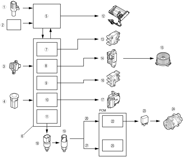
FULL-AUTO AIR CONDITIONER FUNCTION[MZ-CD 1.6 (Y6)]
id0740b3100600
Block Diagram
am3zzn00000502
|
|
1
|
Ambient temperature sensor
|
|
2
|
ECT sensor
|
|
3
|
Cabin temperature sensor
|
|
4
|
Solar radiation sensor
|
|
5
|
PJB and instrument cluster
|
|
6
|
Climate control unit
|
|
7
|
Airflow temperature control
|
|
8
|
Airflow volume control
|
|
9
|
Airflow mode control
|
|
10
|
Air intake control
|
|
11
|
A/C compressor control
|
|
12
|
PTC heater
|
|
13
|
Air mix actuator
|
|
14
|
Power MOS FET
|
|
15
|
Blower motor
|
|
16
|
Airflow mode actuator
|
|
17
|
Air intake actuator
|
|
18
|
Refrigerant pressure switch
|
|
19
|
A/C compressor cycling switch
|
|
20
|
HI pressure
|
|
21
|
Medium pressure
|
|
22
|
A/C cut control
|
|
23
|
A/C relay
|
|
24
|
Magnetic clutch
|
|
25
|
Main fan control
|
Control Table
|
Basic control |
Control description |
Correction control |
|---|---|---|
|
Airflow temperature control
|
Airflow temperature automatic control
|
• Air intake correction
• A/C correction
• PTC heater on/off control
• PTC heater correction
• MAX HOT and MAX COLD correction
• Engine coolant temperature correction
|
|
Airflow volume control
|
Airflow volume automatic control
|
• Engine coolant temperature correction (warm-up correction)
• Vehicle speed correction
• Mild start correction
• MAX HOT and MAX COLD correction
• Window fogging prevention correction at start
• Starting compensation correction
• Defroster correction
• Starting burnt-out prevention function
|
|
Airflow volume manual control
|
• Defroster correction
• Starting burnt-out prevention function
|
|
|
Airflow mode control
|
Airflow mode automatic control
|
• Ambient temperature correction
• Engine coolant temperature correction (warm-up correction)
|
|
Airflow mode manual control
|
―
|
|
|
Air intake control
|
Air intake automatic control
|
• MAX COLD correction
• Defroster correction
• Ambient temperature correction
• A/C OFF correction
|
|
Air intake manual control
|
• Defroster correction
|
|
|
A/C compressor control
|
A/C compressor automatic control
|
• Defroster correction
• Ambient temperature correction
• MAX COLD correction
• Window fogging prevention correction at start
|
|
A/C compressor manual control
|
• Defroster correction
• Ambient temperature correction
• Window fogging prevention correction at start
|
|
Supplementary function |
|---|
|
Fail-safe function
|
|
Sensor signal delay function
|
|
On-board diagnostic function
|
Control Type Transition by Switch Operation
Airflow temperature control, airflow volume control
|
Operation switch |
Airflow temperature control |
Airflow volume control |
||||||||||
|---|---|---|---|---|---|---|---|---|---|---|---|---|
|
Control prior to switch operation |
Control prior to switch operation |
|||||||||||
|
Automatic control |
Automatic control |
Defroster correction |
Manual control |
|||||||||
|
OFF |
1 |
2 |
3 |
4 |
5 |
6 |
7 |
|||||
|
OFF switch
|
Automatic control
|
OFF
|
OFF
|
OFF
|
||||||||
|
AUTO switch
|
Automatic control
|
Automatic control
|
Automatic control
|
Automatic control
|
||||||||
|
Airflow volume control dial
|
+
|
Automatic control
|
Manual control*2
|
Manual control*2
|
1
|
2
|
3
|
4
|
5
|
6
|
7
|
7
|
|
-
|
Automatic control
|
Manual control*3
|
Manual control*3
|
1
|
1
|
1
|
2
|
3
|
4
|
5
|
6
|
|
|
VENT switch
|
Automatic control
|
Automatic control
|
*5
|
No change
|
||||||||
|
BI-LEVEL switch
|
Automatic control
|
Automatic control
|
*5
|
No change
|
||||||||
|
HEAT switch
|
Automatic control
|
Automatic control
|
*5
|
No change
|
||||||||
|
HEAT/DEF switch
|
Automatic control
|
Automatic control
|
*5
|
No change
|
||||||||
|
DEFROSTER switch
|
Automatic control
|
Defroster correction
|
No change
|
Defroster correction
|
||||||||
|
A/C switch
|
Automatic control
|
Automatic control
|
No change
|
No change
|
||||||||
|
REC switch
|
Automatic control
|
Automatic control
|
No change
|
No change
|
||||||||
|
Temperature setting dial*1
|
15.0
|
MAX COLD
|
MAX HI
|
MAX HI
|
No change
|
|||||||
|
15.5—28.5
|
Automatic control
|
Automatic control
|
No change
|
No change
|
||||||||
|
29.0
|
MAX HOT
|
AUTO HI*4
|
AUTO HI
|
No change
|
||||||||
Airflow mode control, air intake control, A/C compressor control
|
Operation switch |
Airflow mode control |
Air intake control |
A/C compressor control |
||||
|---|---|---|---|---|---|---|---|
|
Control prior to switch operation |
Control prior to switch operation |
Control prior to switch operation |
|||||
|
Automatic control |
Manual control |
Automatic control |
Manual control |
Automatic control |
Manual control |
||
|
OFF switch
|
Fixed at mode before turned OFF*2
|
No change*2
|
Fixed at mode before turned OFF*2
|
No change*2
|
OFF
|
OFF
|
|
|
AUTO switch
|
Automatic control
|
Automatic control
|
Automatic control
|
Automatic control
|
Automatic control
|
Automatic control
|
|
|
Airflow volume control dial
|
+
|
Automatic control
|
No change
|
Automatic control
|
No change
|
Automatic control
|
No change
|
|
-
|
Automatic control
|
No change
|
Automatic control
|
No change
|
Automatic control
|
No change
|
|
|
VENT switch
|
No change*2
|
No change*2
|
Automatic control
|
No change*2
|
Automatic control
|
DEFROSTER*3
|
|
|
BI-LEVEL switch
|
No change*2
|
No change*2
|
Automatic control
|
No change*2
|
Automatic control
|
DEFROSTER*3
|
|
|
HEAT switch
|
No change*2
|
No change*2
|
Automatic control
|
No change*2
|
Automatic control
|
DEFROSTER*3
|
|
|
HEAT/DEF switch
|
No change*2
|
No change*2
|
Automatic control
|
No change*2
|
Automatic control
|
DEFROSTER*3
|
|
|
DEFROSTER switch
|
DEFROSTER
|
DEFROSTER
|
Defroster correction
|
Defroster correction
|
Defroster correction
|
Defroster correction
|
|
|
A/C switch
|
Automatic control
|
No change
|
Automatic control
|
No change
|
A/C→OFF
OFF→A/C*4
|
A/C→OFF
OFF→A/C*4
|
|
|
REC switch
|
Automatic control
|
No change
|
FRESH→REC
REC→FRESH
|
FRESH→REC
REC→FRESH
|
Automatic control
|
No change
|
|
|
Temperature setting dial*1
|
15.0
|
Automatic control
|
No change
|
Automatic control
|
No change
|
Automatic control
|
No change
|
|
15.5—28.5
|
Automatic control
|
No change
|
Automatic control
|
No change
|
Automatic control
|
No change
|
|
|
29.0
|
Automatic control
|
No change
|
Automatic control
|
No change
|
Automatic control
|
No change
|
|