 |
am3zzn00000503
MANUAL AIR CONDITIONER CONTROL SYSTEM[MZ-CD 1.6 (Y6)]
id0740b3101000
Block Diagram
am3zzn00000503
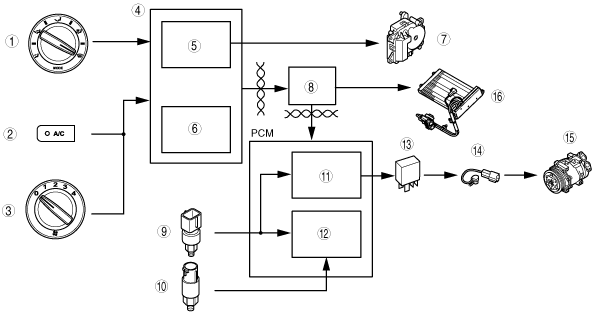
|
|
1
|
Airflow mode selector dial
|
|
2
|
A/C switch
|
|
3
|
Airflow volume control dial
|
|
4
|
Climate control unit
|
|
5
|
Defroster control
|
|
6
|
A/C compressor control
|
|
7
|
Air intake actuator
|
|
8
|
PJB and instrument cluster
|
|
9
|
Refrigerant pressure switch
|
|
10
|
A/C compressor cycling switch
|
|
11
|
Fan control
|
|
12
|
A/C cut-off control
|
|
13
|
A/C relay
|
|
14
|
Stator and thermal protector
|
|
15
|
Magnetic clutch
|
|
16
|
PTC heater
|
Outline of Control System
|
Control name |
Control part |
|---|---|
|
Defroster control
|
Climate control unit
|
|
A/C compressor control
|
Climate control unit
|
|
MAX HOT control
|
Climate control unit
|
Defroster Control
1. When the airflow mode selector dial is turned to DEFROSTER position, a wire moves the airflow mode main link, turning the airflow mode to DEFROSTER.
2. The defroster switch turns on at the same time, and the CPU sends a signal to turn the air intake mode to FRESH.
3. The air intake actuator operates and turns the air intake mode to FRESH.
am3zzn00000504
|
|
1
|
Climate control unit
|
|
2
|
Airflow mode selector dial
|
|
3
|
To DEFROSTER position
|
|
4
|
Defroster switch
|
|
5
|
Wire
|
|
6
|
Airflow mode main link
|
|
7
|
FRESH signal
|
|
8
|
Air intake actuator
|
|
9
|
To FRESH position
|
|
Airflow mode |
Air intake mode (REC switch pushed) |
Defroster control |
|---|---|---|
|
VENT
|
REC Û FRESH
|
–
|
|
BI-LEVEL
|
REC Û FRESH
|
–
|
|
HEAT
|
REC Û FRESH
|
–
|
|
HEAT/DEF
|
REC Û FRESH
|
–
|
|
DEFROSTER
|
FRESH
|
x
|
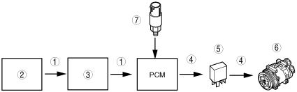
A/C Compressor Control
am3zzn00000505
|
|
1
|
A/C signal
|
|
2
|
Climate control unit
|
|
3
|
PJB and instrument cluster
|
|
4
|
Output
|
|
5
|
A/C relay
|
|
6
|
Magnetic clutch
|
|
7
|
A/C compressor cycling switch
|
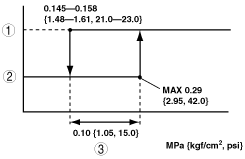
A/C signal on/off control
am3zzn00000579
|
|
1
|
A/C signal ON
|
|
2
|
A/C signal OFF
|
|
3
|
Operation pressure
|
MAX HOT control
am3zzn00000580
|
|
1
|
Airflow volume cntrol dial
|
|
2
|
Temperature control dial
|
|
3
|
Climate control unit
|
|
4
|
PJB
|
|
5
|
PTC heater
|