 |
acxuuw00002512
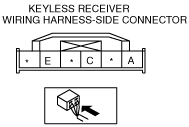
KEYLESS RECEIVER INSPECTION[ADVANCED KEYLESS SYSTEM]
id0914008076b1
1. Disconnect the keyless receiver connector.
2. Connect the negative battery cable.
3. Attach the tester lead to the keyless control module wiring harness-side connector and inspect voltage, continuity, or resistance according to the standard (reference) on the table.
Standard (Reference)
acxuuw00002512
|
|
Terminal |
Signal name |
Connected to |
Measured condition |
Standard |
Inspection item(s) |
|---|---|---|---|---|---|
|
A
|
Power supply
|
Keyless control module
|
Under any condition
|
B+
|
• Keyless control module
• Related wiring harnesses
|
|
C
|
Data
|
Keyless control module
|
Under any condition
|
Continuity detected
|
• Keyless control module
• Related wiring harnesses
|
|
E
|
GND
|
Body ground
|
Under any condition: Inspect for continuity to ground.
|
Continuity detected
|
GND
|