 |
am3zzn00001001
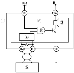
TURN AND HAZARD INDICATOR ALARM CONSTRUCTION/OPERATION
id092200102400
System Wiring Diagram
am3zzn00001001
|
|
1
|
Instrument cluster
|
|
2
|
Microcomputer
|
|
3
|
Indicator buzzer
|
|
4
|
CAN control circuit
|
|
5
|
PJB
|
|
6
|
AND
|
Operation