 |
am3zzn00000739
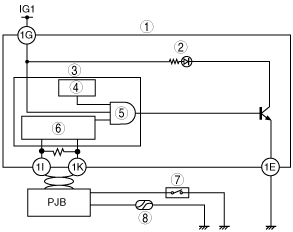
BURNT OUT BULB CHECK FUNCTION CONSTRUCTION/OPERATION
id092200103200
System Wiring Diagram
am3zzn00000739
|
|
1
|
Instrument cluster
|
|
2
|
Brake system warning light
|
|
3
|
Microcomputer
|
|
4
|
Timer
|
|
5
|
AND
|
|
6
|
CAN control circuit
|
|
7
|
Parking brake switch
|
|
8
|
Brake fluid level sensor
|
Operation