 |
am3zzn00000740
ON-BOARD DIAGNOSTIC OPERATION
id092200103400
Malfunction Detection Function
DTC table
|
DTC |
Malfunction location |
Freeze frame data |
|---|---|---|
|
B1202
|
Fuel gauge sender unit circuit malfunction (open circuit)
|
—
|
|
B1204
|
Fuel gauge sender unit circuit malfunction (short to GND)
|
—
|
|
B1342
|
Instrument cluster malfunction
|
—
|
|
B2477
|
Configuration error
|
—
|
|
U0073
|
CAN system communication error (HS-CAN)
|
—
|
|
U0100
|
Communication error to PCM
|
×
|
|
U0101
|
Communication error to TCM
|
×
|
|
U0121
|
Communication error to ABS HU/CM or DSC HU/CM
|
×
|
|
U0131
|
Communication error to EHPAS control module
|
—
|
|
U0140
|
Communication error to PJB
|
×
|
|
U0151
|
Communication error to SAS control module
|
×
|
|
U0214
|
Communication error to keyless control module
|
×
|
|
U1900
|
Communication error to other module
|
×
|
|
U2023
|
Abnormal message from other module
|
×
|
|
U2064
|
Warning light illumination request signal from other modules
|
×
|
|
U2516
|
CAN system communication error (MS-CAN)
|
—
|
Freeze Frame Data
|
Freeze frame data |
Unit |
Note |
|---|---|---|
|
Malfunction type
|
—
|
• Communication errors of other units
• Abnormal messages from the PCM
• Warning light illumination request signal from other units
|
|
Illuminated warning light
|
—
|
Target warning light:
• Air bag system warning light
• Generator warning light
• MIL
• ABS warning light
• Brake system warning light
• AT warning light
• Keyless warning light
|
|
Meter, gauge control status
|
—
|
Target meter, gauge:
• Speedometer
• Tachometer
• Water temperature gauge
|
|
Traveled distance when DTC recorded
|
km
|
Only the last four digits are recorded
|
|
DTC cleared flag
|
Cleared/Not cleared
|
The freeze frame data will not be cleared even if the DTC data is cleared. If a DTC is cleared, a DTC cleared flag 'Cleared' is recorded with the corresponding freeze frame data.
|
DTCs and recorded freeze frame data
Warning light illumination request signal from other modules (U2064)
|
Freeze frame data |
Warning light illumination request unit |
|||||
|---|---|---|---|---|---|---|
|
PCM |
TCM |
ABS HU/CM DSC HU/CM |
SAS control module |
Keyless control module |
||
|
Illuminated warning light
|
Air bag system warning light
|
—
|
—
|
—
|
×
|
—
|
|
Generator warning light
|
×
|
—
|
—
|
—
|
—
|
|
|
MIL
|
×
|
—
|
—
|
—
|
—
|
|
|
ABS warning light
|
—
|
—
|
×
|
—
|
—
|
|
|
Brake system warning light
|
—
|
—
|
×
|
—
|
—
|
|
|
AT warning light
|
×
|
×
|
—
|
—
|
—
|
|
|
Keyless warning light
|
—
|
—
|
—
|
—
|
×
|
|
|
Meter, gauge control status
|
Speedometer
|
—
|
—
|
—
|
—
|
—
|
|
Tachometer
|
—
|
—
|
—
|
—
|
—
|
|
|
Water temperature gauge
|
—
|
—
|
—
|
—
|
—
|
|
Communication errors of other units (U0100, U0101, U0121, U0151, U0214)
|
Freeze frame data |
Unit that communication error occurs |
|||||
|---|---|---|---|---|---|---|
|
PCM (U0100) |
TCM (U0101) |
ABS HU/CM DSC HU/CM (U0121) |
Keyless control module (U0214) |
SAS control module (U0151) |
||
|
Illuminated warning light
|
Air bag system warning light
|
—
|
—
|
—
|
—
|
×
|
|
Generator warning light
|
×*
|
—
|
—
|
—
|
—
|
|
|
MIL
|
×*
|
—
|
—
|
—
|
—
|
|
|
ABS warning light
|
—
|
—
|
×
|
—
|
—
|
|
|
Brake system warning light
|
—
|
—
|
×
|
—
|
—
|
|
|
AT warning light
|
×
|
×
|
—
|
—
|
—
|
|
|
Keyless warning light
|
—
|
—
|
—
|
×
|
—
|
|
|
Meter, gauge control status
|
Speedometer
|
×
|
—
|
—
|
—
|
—
|
|
Tachometer
|
×
|
—
|
—
|
—
|
—
|
|
|
Water temperature gauge
|
×*
|
—
|
—
|
—
|
—
|
|
Abnormal messages from other module (U2023)
|
Freeze frame data |
PCM |
|
|---|---|---|
|
Illuminated warning light
|
Air bag system warning light
|
—
|
|
Generator warning light
|
—
|
|
|
MIL
|
×
|
|
|
ABS warning light
|
—
|
|
|
Brake system warning light
|
—
|
|
|
AT warning light
|
—
|
|
|
Keyless warning light
|
—
|
|
|
Meter, gauge control status
|
Speedometer
|
×
|
|
Tachometer
|
×
|
|
|
Water temperature gauge
|
×
|
|
Input/Output Check Mode
Operation procedure
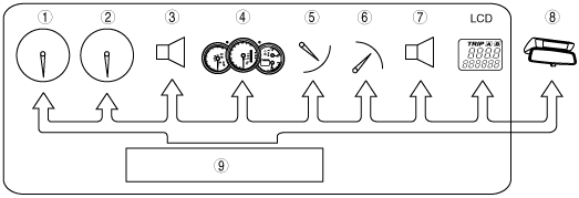
Input circuit check
|
Check code |
Parts sending input signal |
|---|---|
|
08
|
TNS relay
|
|
22
|
Fuel gauge sender unit
|
|
31
|
Key reminder switch (built into the ignition switch)
|
|
55
|
Dimmer switch (built into the instrument cluster)
|
|
62
|
• CAN system
• Cruise control switch
|
am3zzn00000740
|
|
1
|
TNS relay
|
|
2
|
Fuel gauge sender unit
|
|
3
|
Key reminder switch (ignition switch)
|
|
4
|
Dimmer switch
|
|
5
|
Cruise control switch
|
|
6
|
Instrument cluster
|
|
7
|
Microcomputer
|
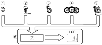
Individual circuit check
|
Check code |
Parts sending input signal |
|---|---|
|
12
|
Speedometer
|
|
13
|
Tachometer
|
|
14
|
Buzzer
|
|
16
|
Fuel-level warning light
|
|
23
|
Fuel gauge
|
|
25
|
Water temperature gauge
|
|
26
|
LCD, warning and indicator light
|
|
32
|
Indicator buzzer
|
|
63
|
Seat belt reminder indicator
|
am3zzn00000741
|
|
1
|
Speedometer
|
|
2
|
Tachometer
|
|
3
|
Buzzer
|
|
4
|
Warning and indicator light
|
|
5
|
Fuel gauge
|
|
6
|
Water temperature gauge
|
|
7
|
Indicator buzzer
|
|
8
|
Seat belt reminder indicator
|
|
9
|
Microcomputer
|
PID/Data Monitor and Record
Monitor item table
|
Monitor item |
Input-output signal/part name |
Unit/State |
Terminal |
|
|---|---|---|---|---|
|
CCNT_HE
|
DTC
|
Number of continuous DTCs
|
—
|
|
|
ECT_GAUGE
|
Water temperature gauge
|
°F
|
°C
|
1I, 1K
|
|
NUMKEYS
|
Number of key ID numbers registered with the vehicle
|
—
|
—
|
|
|
ODO COUNT
|
Odometer
|
m
|
1I, 1K
|
|
|
RPM
|
Tachometer
|
rpm
|
||
|
SPEEDSG
|
Speedometer
|
mph
|
km/h
|
|